
Radial vibration assisted force position control milling and grinding machine tool and control method thereof

A radial vibration, milling and grinding machine tool technology, applied in the control of workpiece feed movement, grinding machine parts, milling machine equipment, etc., can solve the problems of reducing cutting temperature, unstable quality, and reduced function

Pending Publication Date: 2019-07-12
JILIN UNIV
View PDF0 Cites 9 Cited by
  • Summary
  • Abstract
  • Description
  • Claims
  • Application Information

AI Technical Summary

Problems solved by technology

At present, milling and grinding (milling) semi-finishing processes are mainly used in the process of high-precision complex curved surfaces before polishing and finishing. Traditional milling and grinding processes mainly rely on manual operations by skilled workers, which is labor-intensive and efficient. Low quality, unstable quality, the existing milling and forming machine tools have high rigidity, and the coupling problem of milling force and milling cutter head position control has not been well solved. Moreover, in the milling process, especially in the grinding process, The milling cutter head and the workpiece are always in contact, and the grinding fluid is difficult to enter between the cutter head and the surface of the workpiece to be processed, so that the grinding fluid reduces the cutting temperature and takes away the chips, and the abrasive particles in the grinding fluid participate in the cutting It is difficult to guarantee the surface quality and processing efficiency of the processed workpiece, and it is difficult to adapt to the development trend of modern complex surface manufacturing with high precision, high efficiency and low cost.

Method used


Image

  • Radial vibration assisted force position control milling and grinding machine tool and control method thereof
  • Radial vibration assisted force position control milling and grinding machine tool and control method thereof
  • Radial vibration assisted force position control milling and grinding machine tool and control method thereof

Examples


Embodiment Construction

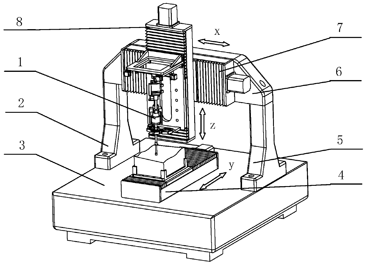
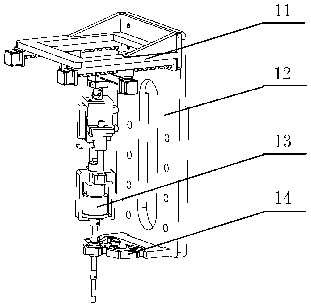
[0058] like figure 1 As shown, it includes a milling tool system 1, a first machine column 2, a machine base 3, a longitudinal moving device 4, a second machine column 5, a machine beam 6, a lateral moving device 7, and a vertical moving device 8, wherein the longitudinal moving device 4. Longitudinal and fixedly installed at the middle position on the upper side of the machine base 3, the first machine column 2 is installed on the left side above the machine base 3 by bolts, and the second machine column 5 is installed on the right side above the machine base 3 by bolts position, the first machine tool column 2 and the second machine tool column 5 are symmetrically distributed with respect to the longitudinal moving device 4, the two ends of the machine tool beam 6 are respectively fixedly installed on the upper ends of the first machine tool column 2 and the second machine tool column 5, and the lateral moving device 7 is horizontally Fixedly installed on the front side of t...


PUM


Abstract

The invention relates to a radial vibration assisted force position control milling and grinding machine tool and a control method of the radial vibration assisted force position control milling and grinding machine tool, and belongs to the field of mechanical precision manufacturing. A longitudinal moving device is longitudinally and fixedly arranged at the middle position of the upper side of amachine tool base, a first machine tool upright post is fixedly arranged at the left side position above the machine tool base through a bolt, a second machine tool upright post is fixedly arranged atthe right position above the machine tool base through a bolt, the first machine tool upright post and the second machine tool upright post are symmetrically distributed about the longitudinal movingdevice, the two ends of a cross beam of the machine tool are fixedly arranged at the upper ends of the first machine tool upright post and the second machine tool upright post respectively, a transverse moving device is transversely and fixedly mounted on the front side face of the cross beam of the machine tool, the vertical moving device is vertically and fixedly mounted on a slide carriage ofthe transverse moving device, and a milling and grinding tool system is vertically and fixedly mounted on a slide carriage of the vertical moving device through bolts. The radial vibration assisted force position control milling and grinding machine tool has the advantages that complex curved surfaces can be machined, milling and grinding force is accurately controlled, machining precision and efficiency are improved, and the machining cost is reduced.

Description

technical field [0001] The invention belongs to the field of mechanical precision manufacturing, and in particular relates to a force-position control milling machine tool and method assisted by radial vibration. Background technique [0002] Today, my country's aerospace, electronics, national defense and many other fields are developing rapidly, which requires more and more high-performance parts with complex surfaces. It is of great significance to study the precision machining technology of complex curved surfaces and develop related equipment to promote the development of the national defense industry and certain high-tech industries. At present, milling and grinding (milling) semi-finishing processes are mainly used in the process of high-precision complex curved surfaces before polishing and finishing. Traditional milling and grinding processes mainly rely on manual operations by skilled workers, which is labor-intensive and efficient. Low quality, unstable quality, ...

Claims


Application Information

Patent Timeline
Patent Type & Authority Applications(China)
IPC IPC(8): B23C3/00B23Q1/25B23Q1/34B24B41/04B24B49/16G05B19/19
CPCB23C3/00B23Q1/25B23Q1/34B24B41/04B24B49/165G05B19/19
Inventor 冀世军张超赵继代汉达贺秋伟杨记龙杨光远于世阳
Owner JILIN UNIV
Learn More