
Centripetal closing type clamp mechanical gripper

A mechanical claw and closed technology, applied in the direction of manipulators, chucks, manufacturing tools, etc., can solve problems such as the dead point of mechanical claws and the problem of grasping spherical objects, and achieve an easy-to-implement, simple structure, and high portability Effect

Pending Publication Date: 2019-07-12
NANJING UNIV OF SCI & TECH
View PDF1 Cites 6 Cited by
  • Summary
  • Abstract
  • Description
  • Claims
  • Application Information

AI Technical Summary

Problems solved by technology

[0005] The purpose of the present invention is to provide a centripetal closed clamping mechanical claw, which solves the problem of the dead point of the existing traditional mechanical claw and the difficulty of grabbing spherical objects

Method used


Image

  • Centripetal closing type clamp mechanical gripper
  • Centripetal closing type clamp mechanical gripper
  • Centripetal closing type clamp mechanical gripper

Examples


Embodiment 1

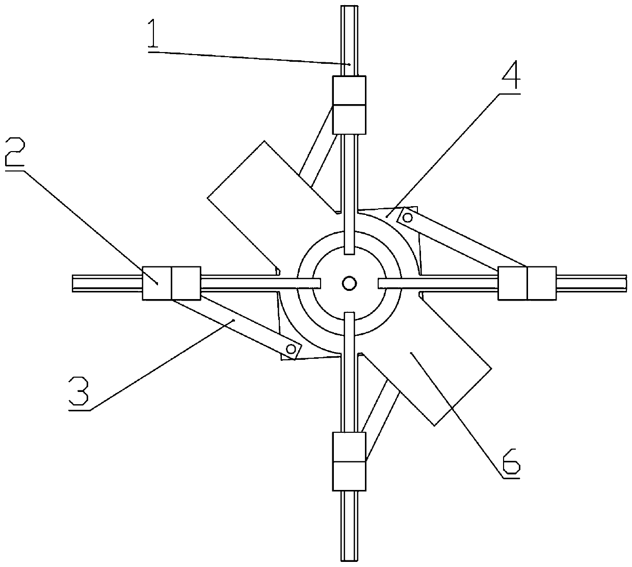
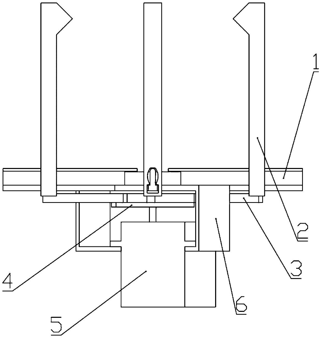
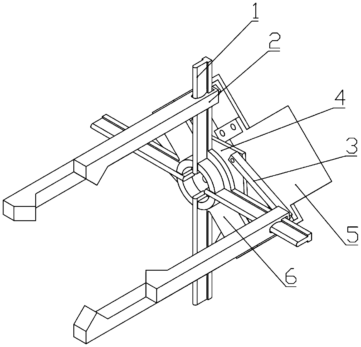
[0029] Combine Figure 1 to Figure 3 , A centripetal closed clamping mechanical claw, including four guide rails 1, four clamping claws 2, four connecting rods 3, a square rudder plate 4, a rudder 5 and a rudder fixed frame 6.

[0030] The steering gear fixing frame 6 includes a bottom plate and two side plates. The two side plates are symmetrically fixed on both sides of the bottom surface of the bottom plate. The steering gear 5 is fixed on the two side plates by bolts. A steering wheel 4 is provided between the bottom plate of the steering gear fixing frame 6 and the steering gear 5, and the output shaft of the steering gear 5 is fixedly connected to the center of the steering gear 4. The four guide rails 1 are evenly distributed on the top surface of the bottom plate. One end of the guide rail 1 is fixed on the bottom plate, and the other end extends out of the bottom plate. Each guide rail 1 is provided with a gripper 2 and four connecting rods 3 are evenly distributed on th...


PUM


Abstract

The invention discloses a centripetal closing type clamp mechanical gripper. The centripetal closing type clamp mechanical gripper can achieve automatic gripping through autonomous control or parameter setting. The centripetal closing type clamp mechanical gripper comprises fixing machine frame guide rails. The lower ends of the fixing machine frame guide rails are coaxially and fixedly connectedwith a steering plate. The steering plate is coaxially and fixedly connected with a steering gear output shaft. The steering gear is connected with the fixing machine frame guide rails. The four corners of the steering plate are each hinged to one end of a connection rod. The other ends of the connection rods are hinged to four gripping jaws. The gripping jaws are connected to the guide rails. Thefour gripping jaws are arranged in four directions of the steering gear output shaft at equal intervals. The centripetal closing type clamp mechanical gripper is simple in structure, simple in control method and high in transportability. By controlling the flare angle, a spherical object can be stably gripped, and the shape of the object is not changed. During design of the centripetal closing type clamp mechanical gripper, the part wear problem is taken into full consideration, and parts are convenient to replace.

Description

Technical field [0001] The invention relates to a robot end clamping technology, in particular to a centripetal closed clamping mechanical claw. Background technique [0002] In the field of robotics, mechanical clamping devices can complete various sorting and handling tasks, so the design of the robot's end clamping system is particularly important. [0003] Chinese patent CN 206982703 U proposes a two-finger closed mechanical claw controlled by a steering gear and driven by a gear. The statement proposes that it can achieve the effect of clamping small spheres, but the clamping effect is not ideal in practical applications. Falling off; and the gear and the claw are in an integrated structure. The entire clamping claw needs to be replaced after the gear is worn. [0004] Most of the existing clamping mechanical claws have the effect of two-finger opening and closing movement on a two-dimensional plane to complete the placement and clamping of the object, and the clamping ability ...

Claims


Application Information

Patent Timeline
Patent Type & Authority Applications(China)
IPC IPC(8): B25J15/00B25J15/10
CPCB25J15/00B25J15/0033B25J15/10
Inventor 孙运江张志安周航
Owner NANJING UNIV OF SCI & TECH
Learn More