Robot joint structure and robot joint structure assembly method

A technology of a robot joint and an assembly method, applied in the field of robots, can solve the problems affecting the structural performance and life of the robot joint, the high requirements for the assembly ability of the robot connector, and the limited volume design of the robot, so as to achieve simple and convenient installation and maintenance. High operational feasibility and stability, avoiding the cumulative effect of machining errors and assembly errors

Active Publication Date: 2019-07-12
SHENZHEN INOVANCE TECH
View PDF10 Cites 5 Cited by
  • Summary
  • Abstract
  • Description
  • Claims
  • Application Information

AI Technical Summary

Problems solved by technology

[0008] The embodiments of the present invention aim at the joint structure of the above-mentioned robot. The method of adding connectors to realize the driving connection needs to occupy a large space, so that the volume design of the robot is limited, the connectors may have processing errors, and there is a potential to increase the overall error of the robot. Risk, which is not conducive to the realization of high-precision operations of the robot, and the connectors have high requirements for assembly capabilities. Once the connectors have assembly problems, it is easy to cause vibration and noise of the robot joints, which in turn affects the performance and life of the robot joint structure and assembly efficiency. low, and it is difficult to disassemble and install the motor after the assembly of the whole machine, and provide a robot joint structure and an assembly method for the robot joint structure

Method used


Image

  • Robot joint structure and robot joint structure assembly method
  • Robot joint structure and robot joint structure assembly method
  • Robot joint structure and robot joint structure assembly method

Examples


Embodiment Construction

[0038]In order to make the object, technical solution and advantages of the present invention clearer, the present invention will be further described in detail below in conjunction with the accompanying drawings and embodiments. It should be understood that the specific embodiments described here are only used to explain the present invention, not to limit the present invention.

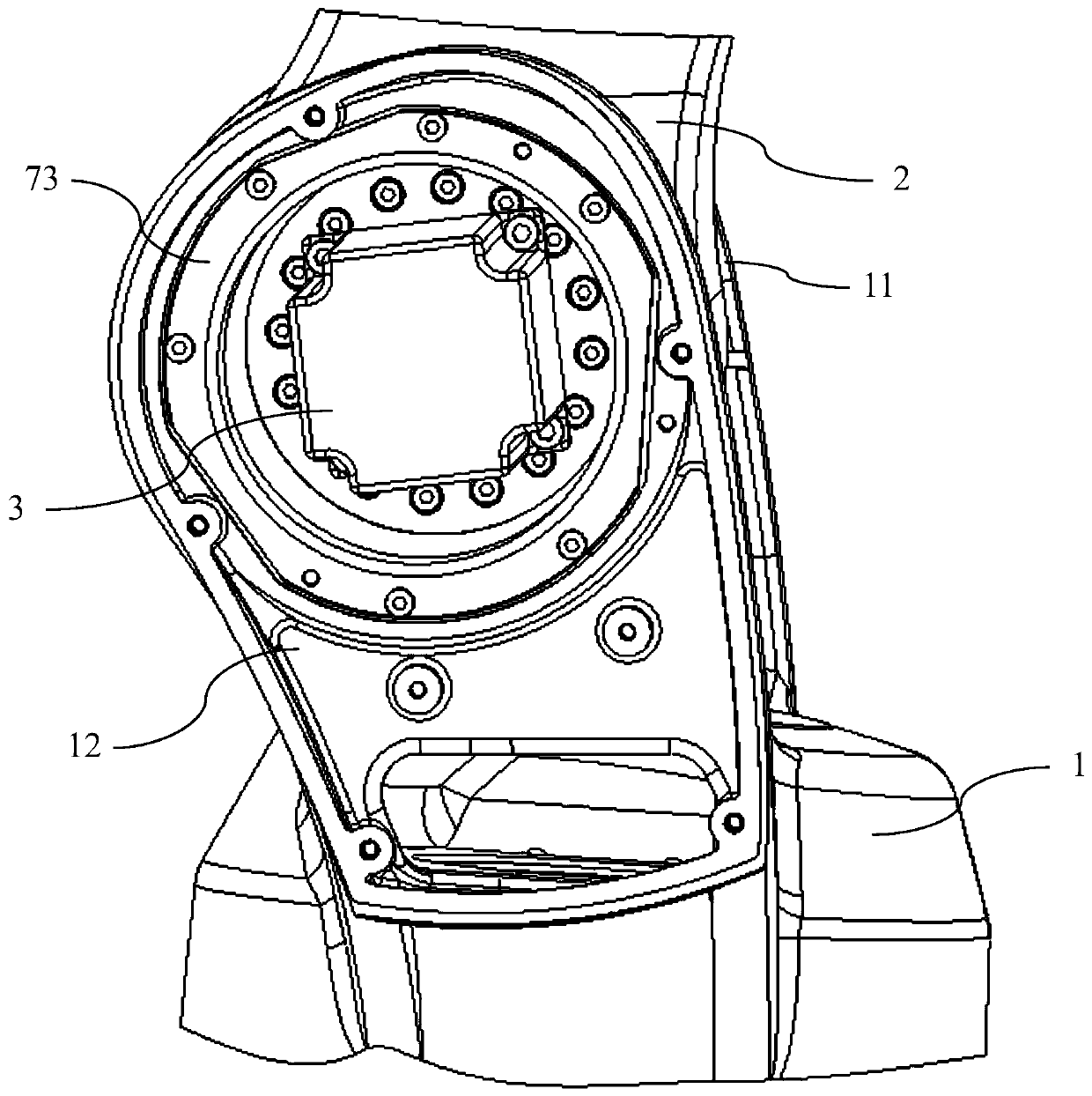
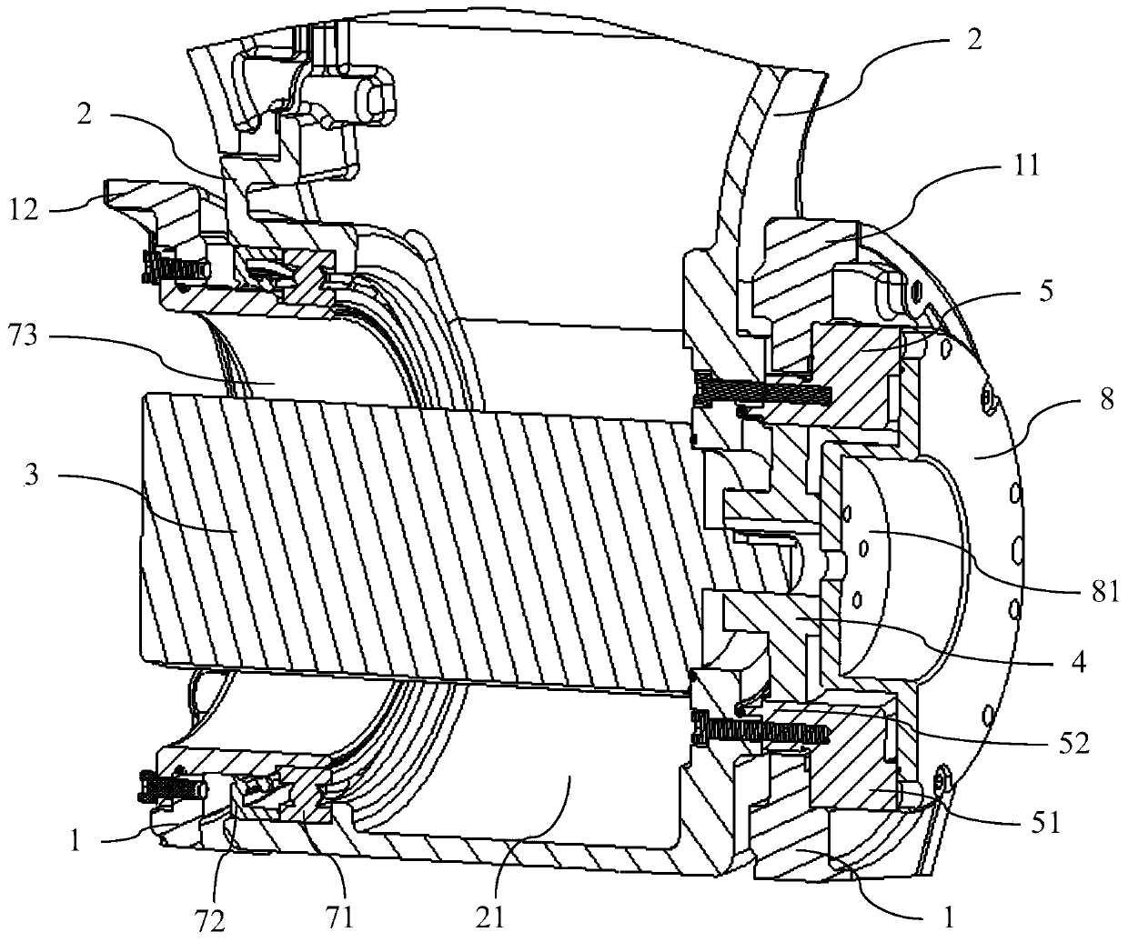
[0039] like figure 1 As shown, it is a schematic structural diagram of the robot joint structure provided by the embodiment of the present invention, which can be applied in the field of robotics, especially in the robot joint structure requiring a small volume. combine figure 2 As shown, the robot joint structure in this embodiment is used to connect the rocker arm 1 and the base 2 of the robot, and realize the relative rotation between the rocker arm 1 and the base 2, wherein the rocker arm 1 includes a Mounting cavity 21 .

[0040] Above-mentioned robot joint structure comprises drive motor 3...


PUM


Abstract

The invention provides a robot joint structure and a robot joint structure assembly method. The robot joint structure comprises a rocker arm and a base, the rocker arm comprises a mounting cavity, therobot joint structure comprises a driving motor, a wave generator and a reducer rigid and soft wheel member, and the wave generator is mounted to the reducer rigid and soft wheel member; the reducerrigid and soft wheel member is installed in the manner that a first part is fixed to the rocker arm and a second part is fixed to the base, and the reducer rigid and soft wheel member is located at afirst end opening of the mounting cavity; and the driving motor is inserted into the mounting cavity from a second end opening of the mounting cavity and is fixed to the rocker arm, and an output shaft of the driving motor is directly in matched transmission with an inner hole of the wave generator. By means of the robot joint structure and the robot joint structure assembly method, the output shaft of the driving motor is directly connected to the inner hole of the wave generator, the size of the robot joint structure can be decreased, and the designability of the applicable range and the volume is improved.

Description

technical field [0001] Embodiments of the present invention relate to the field of robots, and more specifically, relate to a robot joint structure and an assembly method for the robot joint structure. Background technique [0002] Industrial robots are an important automation equipment in the modern manufacturing industry. They have been widely used in CNC (Computerized Numerical Control, computer numerical control technology) loading and unloading, mobile phone shell grinding, metal grinding and other application fields. Manufacturing with industrial robots as the core The demand for equipment is increasing day by day. In the research and development process of the multi-joint robot body, the design of the robot joint structure scheme is a crucial link, and it is one of the technical cores of the research and development of the mechanical part of the robot. [0003] The existing robot joint structure generally adds a connecting piece between the drive motor and the reduce...

Claims


Application Information

Patent Timeline
Patent Type & Authority Applications(China)
IPC IPC(8): B25J17/02B25J9/12
CPCB25J17/02B25J9/126
Inventor 沈石华朱家增祁斌弓鹏伟
Owner SHENZHEN INOVANCE TECH
Why Eureka
Try Eureka