Drainage stand pipe structure suitable for top cover development and arrangement method of drainage stand pipe structure

A drainage standpipe and cover plate technology, which is applied in the direction of water supply equipment, roof drainage, sewer pipe system, etc., can solve the problems of design defects, poor drainage structure landscape effect, small drainage pipe diameter, etc., to reduce the division of available space , Improve the stability of settings, and ensure the effect of stable settings

Pending Publication Date: 2019-07-12
CHINA RAILWAY SIYUAN SURVEY & DESIGN GRP
View PDF0 Cites 3 Cited by
  • Summary
  • Abstract
  • Description
  • Claims
  • Application Information

AI Technical Summary

Problems solved by technology

At the same time, because there are many impurities in the rainwater in the development of the superstructure, and for large-scale roof drainage, the siphon drainage system is generally used in the prior art, but the diameter of the drainage pipe in this system is often small, and the rainwater bucket The structure is fine, and it is easy to be blocked by larger impurities in the water, especially when larger impurities such as cloth strips and fluff pass through the rainwater bucket
[0004] For the above-mentioned drainage pipes developed by the superstructure, the gravity drainage scheme is generally adopted in the prior art. In this scheme, the drainage pipe with a larger diameter is used for drainage. Although it can meet the drainage requirements of the superstructure development project to a certain extent, But there are still some defects
Specifically, the main defects of the drainage structure developed by the existing superstructure are as follows: First, the diameter of the drainage pipe in the existing drainage structure is relatively large, which has a great impact on the building facade of the structure under the construction, and generally requires Set up a dry-hanging system to seal the drainage pipes, and the landscape effect of the drainage structure is poor. In addition, after the existing gravity drainage structure is installed, the buried section of the drainage pipes is prone to ground subsidence, which in turn leads to the overall subsidence of the drainage structure. The connection between the drainage pipe structure and the upper cover is loose, which leads to the problem of drainage leakage, which affects the normal use of the facilities on and under the cover, and has obvious design defects and application limitations.

Method used


Image

  • Drainage stand pipe structure suitable for top cover development and arrangement method of drainage stand pipe structure
  • Drainage stand pipe structure suitable for top cover development and arrangement method of drainage stand pipe structure
  • Drainage stand pipe structure suitable for top cover development and arrangement method of drainage stand pipe structure

Examples


Embodiment Construction

[0036] In order to make the object, technical solution and advantages of the present invention clearer, the present invention will be further described in detail below in conjunction with the accompanying drawings and embodiments. It should be understood that the specific embodiments described here are only used to explain the present invention, not to limit the present invention.

[0037] In addition, the technical features involved in the various embodiments of the present invention described below can be combined with each other as long as they do not constitute a conflict with each other.

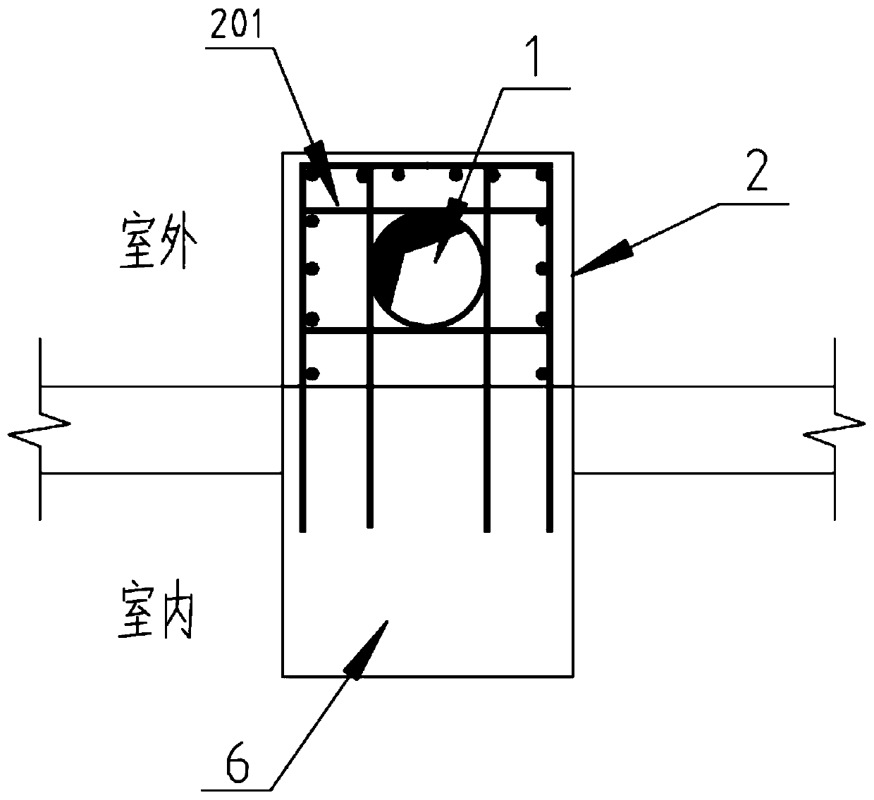
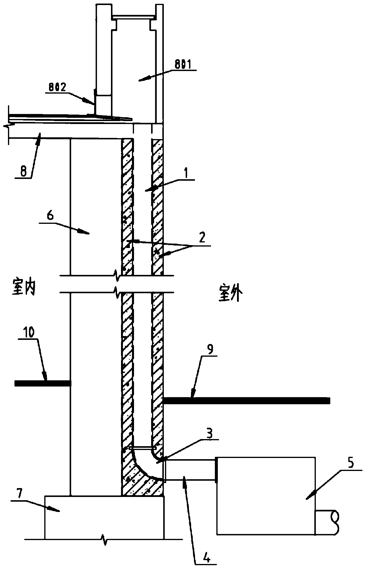
[0038] In the preferred embodiment of the present invention, the drainage standpipe structure applicable to the development of the upper cover is as follows: figure 1 and figure 2 As shown in , it is not difficult to see from the diagram that the drainage standpipe structure in the preferred embodiment is arranged corresponding to the frame column 6 of the upper cover development struct...


PUM


Abstract

The invention discloses a drainage stand pipe structure suitable for top cover development and arrangement method of the drainage stand pipe structure, and belongs to the related technical field of upper cover development. The drainage stand pipe is arranged correspondingly to a frame column at the bottom of an upper cover plate, a constructional column is arranged correspondingly to the drainagestand pipe on the side, near the outdoor, of the frame column, the drainage stand pipe is buried in the constructional column as a permanent formwork of the constructional column, the constructional column and the bottom surface of the upper cover plate, the side wall surface of the frame column and the top surface of a structural cushion cap are correspondingly and fixedly connected through a reinforcement planting mode, and the relative fixing arrangement of the drainage stand pipe and the frame column is achieved. According to the drainage stand pipe, the structure is simple, arrangement steps are simple and convenient, stable arrangement of the drainage stand pipe between the upper cover plate and an energy dissipation well in the process of upper cover development can be effectively achieved, the leakage problem caused by settlement of the drainage stand pipe is avoided, the arrangement landscape of the drainage stand pipe structure can be effectively improved, segmentation and occupation of the space under the cover are reduced, and good application prospects and popularization value are achieved.

Description

technical field [0001] The invention belongs to the related technical field of upper cover development, and in particular relates to a drainage standpipe structure suitable for upper cover development and a setting method thereof. Background technique [0002] With the continuous development of my country's economic construction, more and more rail transit lines, railway depots, parking lots, etc. need to be constructed or planned to be constructed. In addition, the country saves land, improves land use efficiency, and realizes harmonious urban environment. The requirement of sustainable development has led to the emergence of a large number of superstructure buildings constructed and developed on the upper part of the depot or parking lot. The lower part of this type of building is often a large-bay vehicle warehouse, maintenance workshop, etc., which become the space for the depot under the cover, and the upper part is the cover. The frame-supported shear wall structure of t...

Claims


Application Information

Patent Timeline
IPC IPC(8): E04D13/08E03F3/04E03F3/06
CPCE04D13/08E03F3/04E03F3/06E04D2013/0826E04D2013/084E04D2013/0893
Inventor 胡凤祥梁田贠毓江胜学
Owner CHINA RAILWAY SIYUAN SURVEY & DESIGN GRP
Why Eureka
Try Eureka