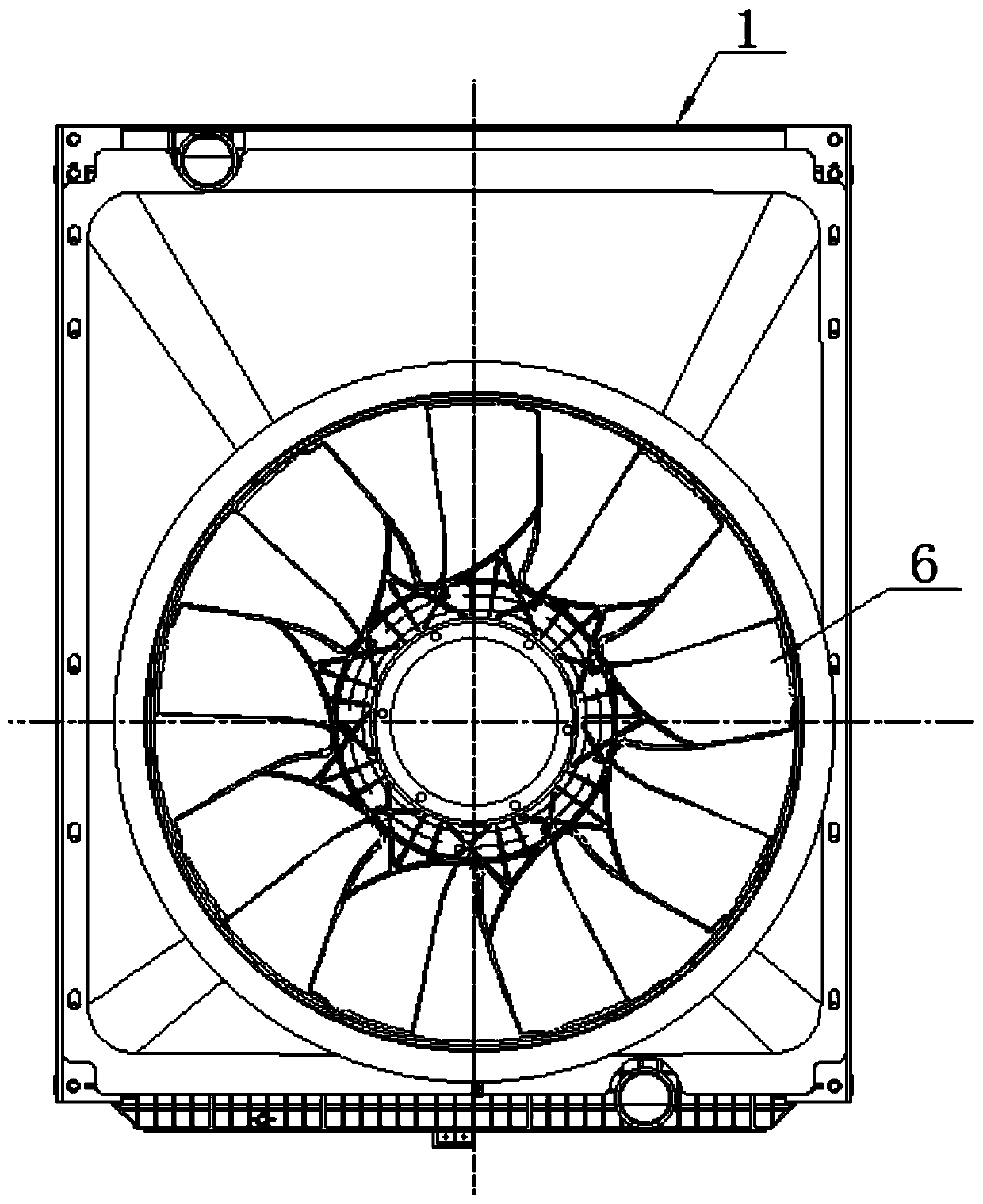
Flow guiding cooling system composed of annular fan and wind protecting ring
A technology of diversion cooling and wind protection ring, which is applied in the direction of engine cooling, engine components, machines/engines, etc. It can solve the problems of reduced cooling fan performance, low cooling fan efficiency, high manufacturing cost, etc., and achieves simple structure and high efficiency. , low cost effect
- Summary
- Abstract
- Description
- Claims
- Application Information
AI Technical Summary
Problems solved by technology
Method used
Image

Examples
Embodiment 1
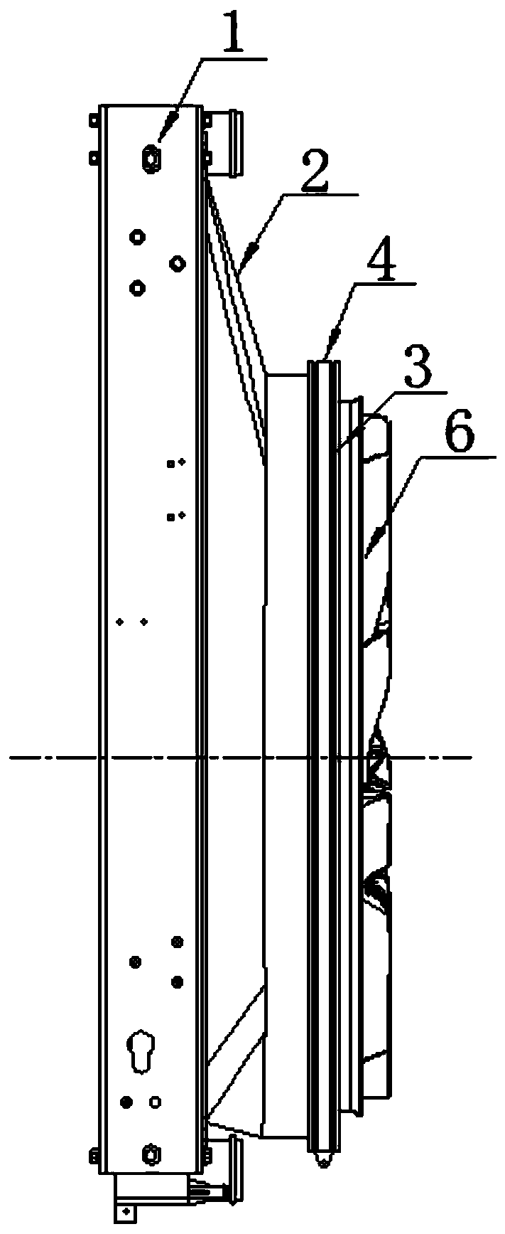
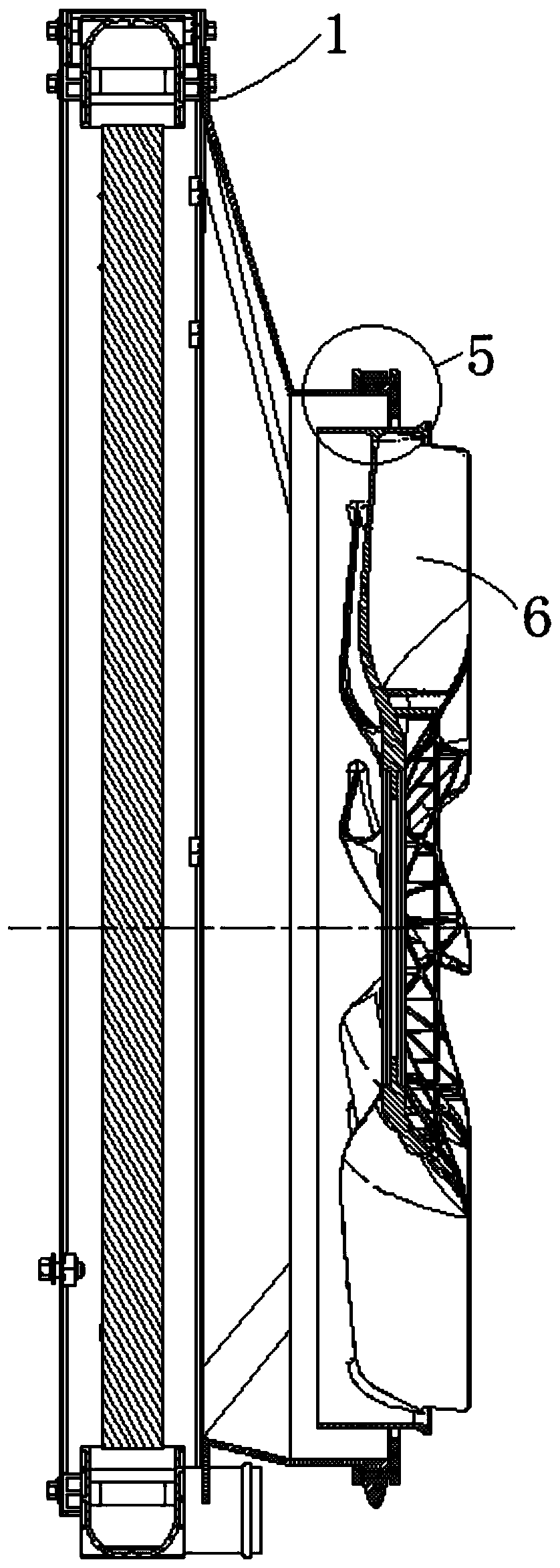
[0027] The cooling package frame 1 is fixed on the outside of the radiator, one end of the wind protection ring 2 is fixed with the cooling package frame 1, and the other end of the wind protection ring 2 is integrally formed with one end of the wind protection ring protrusion 51, and the wind protection ring The other end of the protrusion 51 is a continuous or discontinuous circumferential protrusion, and the baffle positioning end 53 provided at one end of the baffle end 52 is snap-connected with the protrusion 51 of the wind protection ring, and the other end of the baffle end 52 is connected with the The baffle 3 is an integrally formed structure, the fixing device 4 fixes the positioning end 53 of the baffle on the protrusion 51 of the wind protection ring, and the hoop is fixed to fix the baffle 3 on the wind protection ring 2 through the hoop, and the ring The cross-section of the hoop is rectangular, and the fixing device 4 is fixed by a hoop, and the flow-stopping end...
Embodiment 2
[0030] The cooling package frame 1 is fixed on the outside of the radiator, one end of the wind protection ring 2 is fixed together with the cooling package frame 1, the other end of the wind protection ring 2 is integrally formed with one end of the wind protection ring protrusion 51, and the flow blocking end The baffle positioning end 53 provided at one end of the 52 is fixed with the wind protection ring protrusion 51 by threaded connection, the fixing device 4 fixes the baffle positioning end 53 on the wind protection ring protrusion 51, and the flow baffle end 52 The other end and the baffle 3 are integrally formed, the fixing device 4 is fixed by screws, and the baffle 3 is fixed on the wind protection ring 2 by the screws, and the baffle end 52 is provided with a return port 54, The return port 54 is a rectangular hole, the height of the return port 54 is 25mm, and the height of the return port 54 is less than 1 / 3 of the height from the bottom of the wind protection rin...
Embodiment 3
[0033] The cooling package frame 1 is fixed on the outside of the radiator, one end of the wind protection ring 2 is fixed together with the cooling package frame 1, the other end of the wind protection ring 2 is integrally formed with one end of the wind protection ring protrusion 51, and the flow blocking end The baffle positioning end 53 provided at one end of 52 is fastened with the wind protection ring protrusion 51 by welding, and the fixing device 4 fixes the baffle positioning end 53 on the wind protection ring protrusion 51, and the flow baffle end 52 The other end and the baffle 3 are integrally formed, and the fixing device 4 is fixed by a buckle, and the baffle 3 is fixed on the wind protection ring 2 by the buckle, and the baffle end 52 is provided with a return port 54, the return port 54 is a through hole, the height of the return port 54 is 28mm, and the height of the return port 54 is less than 1 / 4 of the height from the bottom of the wind protection ring protr...
PUM
 Abstract
Description
Claims
Application Information