Underwater inspecting system
A technology of inspection system and base station, applied in the field of inspection, can solve the problems of pipeline transmission medium loss, pipeline water pollution, locate pipeline leakage points, etc., and achieve the effect of reducing pipeline transmission medium loss
- Summary
- Abstract
- Description
- Claims
- Application Information
AI Technical Summary
Problems solved by technology
Method used
Image

Examples
Embodiment 1
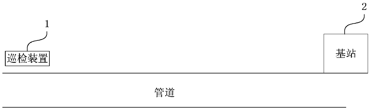
[0041] figure 1 It is a structural schematic diagram of an underwater inspection system provided by Embodiment 1 of the present invention. This embodiment is applicable to detecting the position of the leakage point of an underwater pipeline. The underwater inspection system provided by the embodiment of the present invention can be used as an underwater inspection system. The sub-system of the pipeline transmission system assists in the transmission of the medium in the pipeline. Typically, in the offshore oil and gas production system, the underwater inspection system can be used to detect the leakage point of the submarine pipeline and assist in the completion of the oil and gas transfer from the seabed to the land. Transmission work.
[0042] Such as figure 1 As shown, the underwater inspection system includes: a base station 2 and an inspection device 1 .
[0043] The base station 2 is arranged on the pipeline, and is used for sending positioning acoustic wave signals t...
Embodiment 2
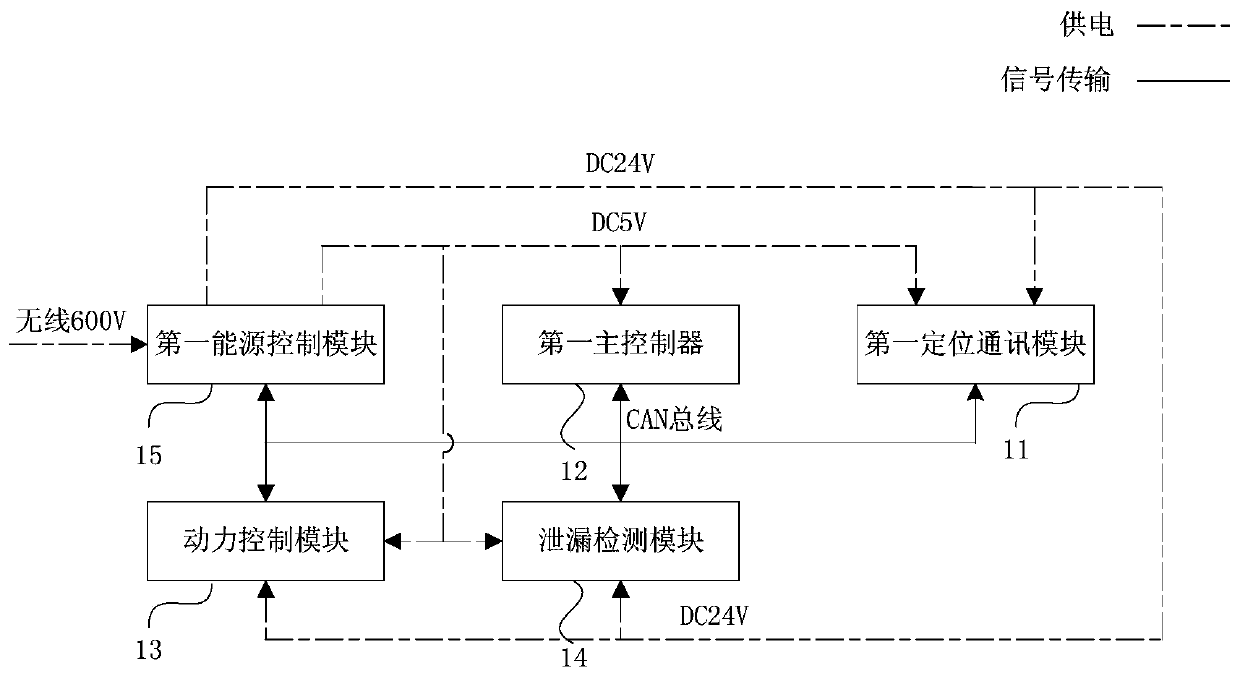
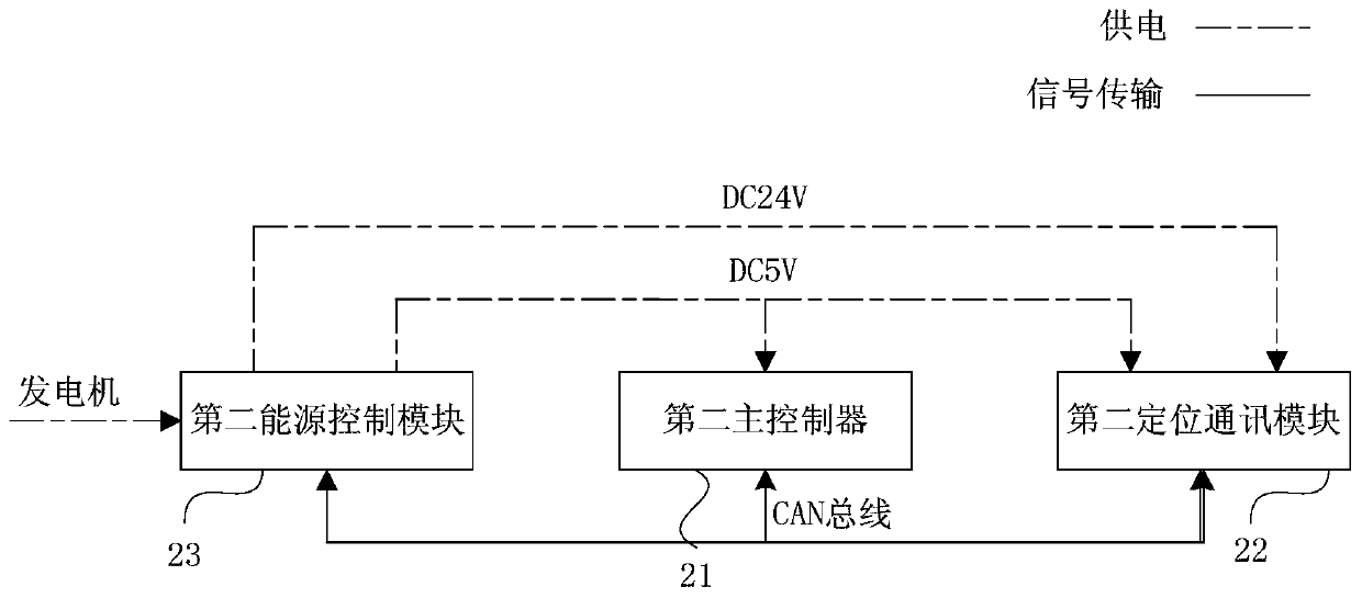
[0058] Embodiment 2 of the present invention provides an underwater inspection system. This embodiment further explains on the basis of the previous embodiment, and provides the specific structure of the inspection device 1 and the base station 2 in the underwater inspection system. The following is combined Figure 2a and 2b An underwater inspection system provided in Embodiment 2 will be described.
[0059] like Figure 2a As shown, the inspection device 1 includes: a first positioning communication module 11 , a first main controller 12 , a power control module 13 , a leakage detection module 14 and a first energy control module 15 .
[0060] In this embodiment, the first main controller 12 of the inspection device 1 is a processing terminal for scheduling and managing other modules in the inspection device 1 .
[0061] It should be noted that, in this embodiment, the modules or the main controller in the inspection device 1 all realize data communication through electric...
Embodiment 3
[0104] Embodiment 3 of the present invention provides an underwater inspection system. This embodiment is further described on the basis of the above embodiments, and provides a leak detection module, a first positioning communication module 11 and a first energy control module in the inspection device 1. The specific structure of module 15 is combined below Figure 3a , 3b and 3e describe an underwater inspection system provided in the third embodiment.
[0105] It should be noted that, in this embodiment, the units or controllers in the module realize data communication through electrical connection, and the drawings in this embodiment only provide a preferred electrical connection manner. Moreover, in this embodiment, the unit or the controller needs a preset type of electric energy to provide energy for it, and the drawings in this embodiment only provide a preferred power supply mode.
[0106] like Figure 3a As shown, the leak detection module 14 includes: a leak dete...
PUM
 Abstract
Description
Claims
Application Information
 - R&D
- Intellectual Property
- Life Sciences
- Materials
- Tech Scout
- Unparalleled Data Quality
- Higher Quality Content
- 60% Fewer Hallucinations
Browse by: Latest US Patents, China's latest patents, Technical Efficacy Thesaurus, Application Domain, Technology Topic, Popular Technical Reports.
© 2025 PatSnap. All rights reserved.Legal|Privacy policy|Modern Slavery Act Transparency Statement|Sitemap|About US| Contact US: help@patsnap.com