
Underwater inspection system

A technology of inspection system and base station, applied in the field of inspection, can solve the problems of pipeline transmission medium loss, pipeline water pollution, locate pipeline leakage points, etc., and achieve the effect of reducing pipeline transmission medium loss

Active Publication Date: 2020-09-08
MEIZUAN SHENHAI ENERGY TECH RES & DEV SHANGHAI CO LTD
View PDF7 Cites 0 Cited by
  • Summary
  • Abstract
  • Description
  • Claims
  • Application Information

AI Technical Summary

Problems solved by technology

[0004] However, in the initial stage of pipeline leakage, due to the small scale of the leakage point, it is difficult to quickly and accurately locate the position of the pipeline leakage point due to the limitation of the installation position and number of detection devices in the existing technology. When it is discovered, it has already caused the loss of the pipeline transmission medium, and even caused some pollution to the water quality around the pipeline.

Method used


Image

  • Underwater inspection system
  • Underwater inspection system
  • Underwater inspection system

Examples


Embodiment 1

[0041] figure 1 It is a structural schematic diagram of an underwater inspection system provided by Embodiment 1 of the present invention. This embodiment is applicable to detecting the position of the leakage point of an underwater pipeline. The underwater inspection system provided by the embodiment of the present invention can be used as an underwater inspection system. The sub-system of the pipeline transmission system assists in the transmission of the medium in the pipeline. Typically, in the offshore oil and gas production system, the underwater inspection system can be used to detect the leakage point of the submarine pipeline and assist in the completion of the oil and gas transfer from the seabed to the land. Transmission work.

[0042] Such as figure 1 As shown, the underwater inspection system includes: a base station 2 and an inspection device 1 .

[0043] The base station 2 is arranged on the pipeline, and is used for sending positioning acoustic wave signals t...

Embodiment 2

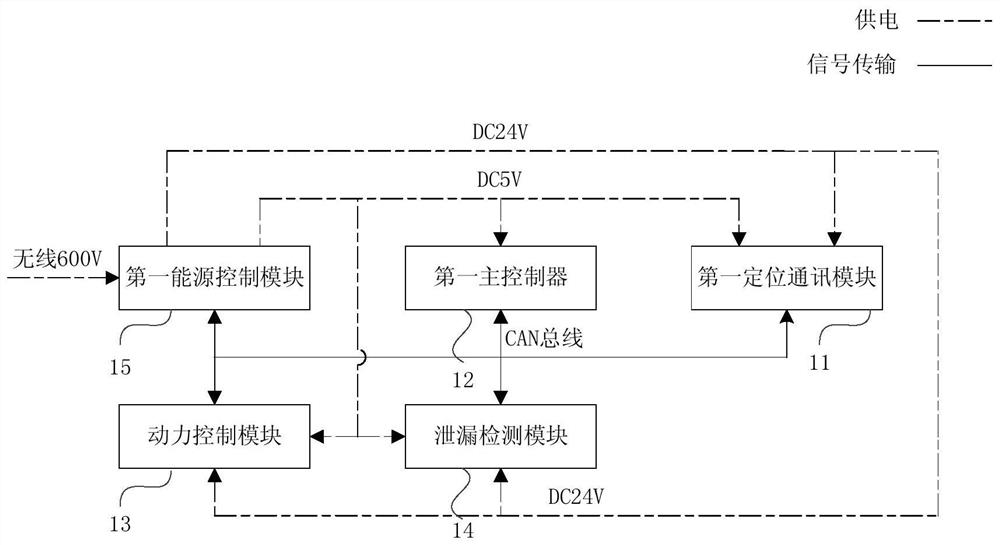
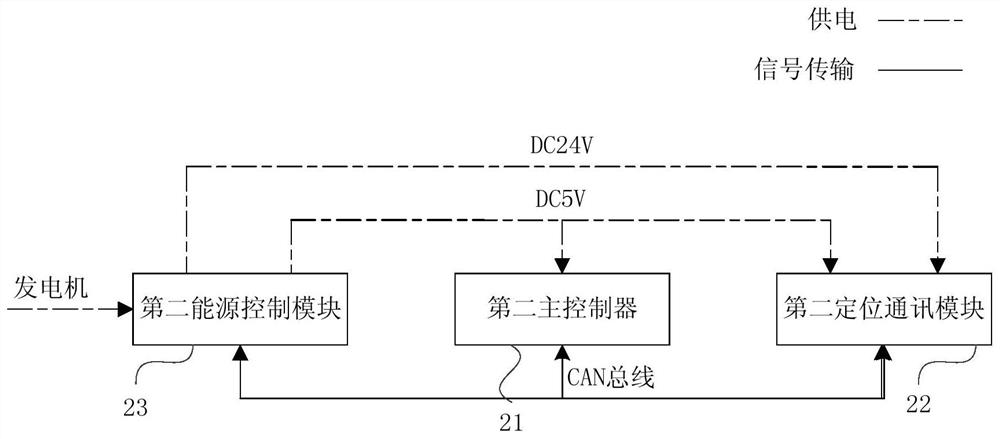
[0058] Embodiment 2 of the present invention provides an underwater inspection system. This embodiment further explains on the basis of the previous embodiment, and provides the specific structure of the inspection device 1 and the base station 2 in the underwater inspection system. The following is combined Figure 2a with 2b An underwater inspection system provided in Embodiment 2 will be described.

[0059] Such as Figure 2a As shown, the inspection device 1 includes: a first positioning communication module 11 , a first main controller 12 , a power control module 13 , a leakage detection module 14 and a first energy control module 15 .

[0060] In this embodiment, the first main controller 12 of the inspection device 1 is a processing terminal for scheduling and managing other modules in the inspection device 1 .

[0061] It should be noted that, in this embodiment, the modules or the main controller in the inspection device 1 all realize data communication through elec...

Embodiment 3

[0104] Embodiment 3 of the present invention provides an underwater inspection system. This embodiment is further described on the basis of the above embodiments, and provides a leak detection module, a first positioning communication module 11 and a first energy control module in the inspection device 1. The specific structure of module 15 is combined below Figure 3a , 3b and 3e describe an underwater inspection system provided in the third embodiment.

[0105] It should be noted that, in this embodiment, the units or controllers in the module realize data communication through electrical connection, and the drawings in this embodiment only provide a preferred electrical connection manner. Moreover, in this embodiment, the unit or the controller needs a preset type of electric energy to provide energy for it, and the drawings in this embodiment only provide a preferred power supply mode.

[0106] Such as Figure 3a As shown, the leak detection module 14 includes: a leak d...


PUM


Abstract

The embodiment of the invention discloses an underwater inspecting system. The system comprises an inspecting device and a base station; the base station is arranged on a pipeline and used for transmission a positioning sonic wave signal to the inspecting device, and the inspecting device is used for receiving the positioning sonic wave signal and determining the relative position of a pipeline leakage point and the inspecting device according to the movement of the positioning sonic wave signal towards the base station and the real-time collection of the sonic wave signal of the pipeline leakage point in the moving process; the inspecting device is further used for transmitting a sonic wave signal requesting for charging, receiving an infrared signal to determine the moving direction towards a charging port of the base station based on the infrared signal, and butting with the charging port of the base station based on the moving direction to receive energy provided by the base station, and the base station is further used for transmitting the infrared signal to the inspecting device based on the sonic wave signal requesting for charging. The system has the advantages that the position of the pipeline leakage point can be rapidly and accurately positioned to reduce the loss of a pipeline transmission medium.

Description

technical field [0001] The embodiments of the present invention relate to inspection technologies, and in particular to an underwater inspection system. Background technique [0002] Since the 1950s, the amount of underwater pipeline laying has been increasing, from the past laying across rivers to the current laying across deep seas, realizing the transmission network of underwater oil and gas. [0003] Because underwater oil and gas pipelines are soaked in water, they will be corroded by chemicals and organisms. In the long run, the wall thickness of the pipeline will gradually decrease, which will lead to the leakage of the transmission medium in the pipeline. The existing technology mainly detects the pressure and flow of the pipeline by installing a detection device on the pipeline, so as to determine the position of the leakage point of the pipeline. [0004] However, in the initial stage of pipeline leakage, due to the small scale of the leakage point, it is difficul...

Claims


Application Information

Patent Timeline
Patent Type & Authority Patents(China)
IPC IPC(8): F17D5/06G01S5/18
CPCF17D5/06G01S5/18
Inventor 黄河生祥
Owner MEIZUAN SHENHAI ENERGY TECH RES & DEV SHANGHAI CO LTD
Learn More