A prefabricated steel structure node experimental device
A technology for experimental devices and steel structures, applied in measuring devices, building structures, buildings, etc., can solve the problems of lack of experimental devices and lack of bolted joints, and achieve the effect of ingenious structure and strong practicability
- Summary
- Abstract
- Description
- Claims
- Application Information
AI Technical Summary
Problems solved by technology
Method used
Image
Examples
Embodiment 1
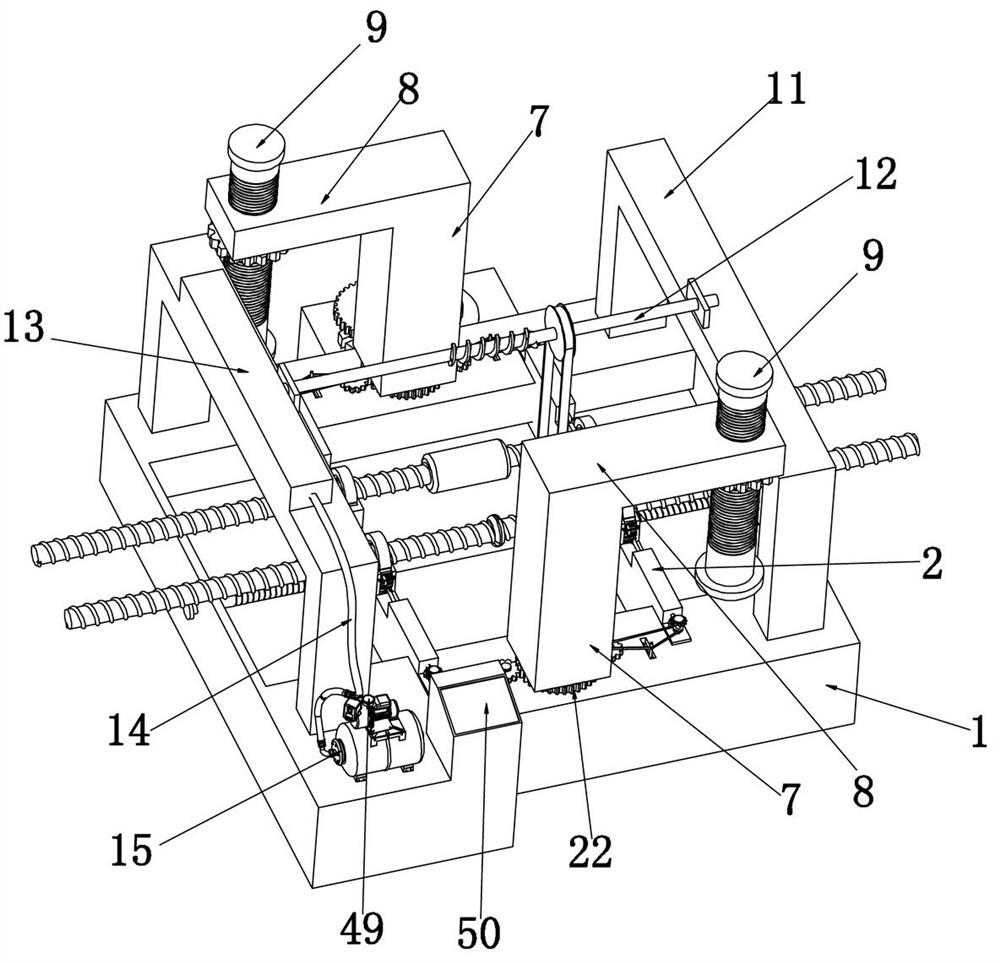
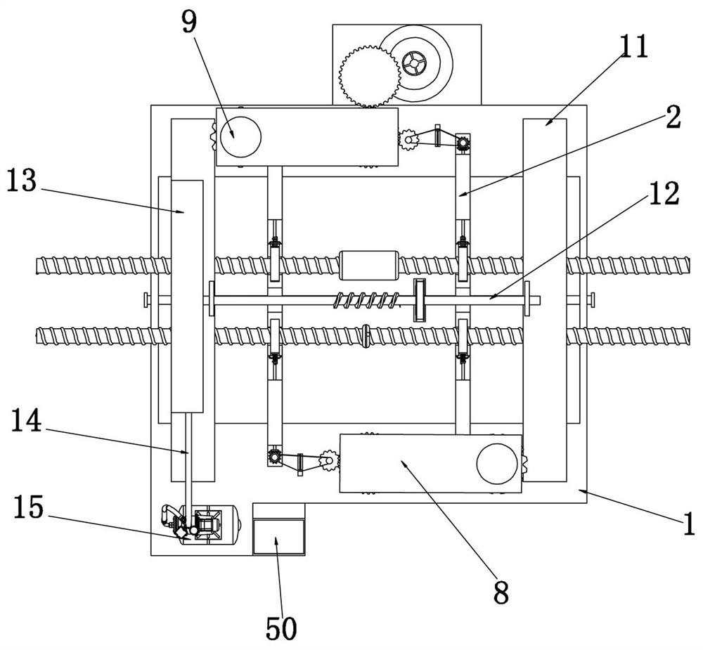
[0045] Embodiment 1, the present invention is an experimental device for fabricated steel structure nodes, please refer to figure 1 and figure 2 , the experimental object is two fabricated steel structures, one of which is connected by bolt welding, and the other is connected by bolt connection (here, specifically, the connection is made by using a steel sleeve, and the steel bar The sleeve is also known as the steel bar joint: it is used to connect the steel bar and has a connecting piece with an internal thread corresponding to the wire head thread; simple construction process: the end of the steel bar is processed into a straight thread by rolling process, and the corresponding connecting sleeve is used to connect The two steel bars are connected to each other (of course, the experimental device here), including a shell 1 with an inner hollow upper opening, and the shell 1 is fixed on the table body or the ground. It is used as a support body and is made of cast iron. The ...
Embodiment 2
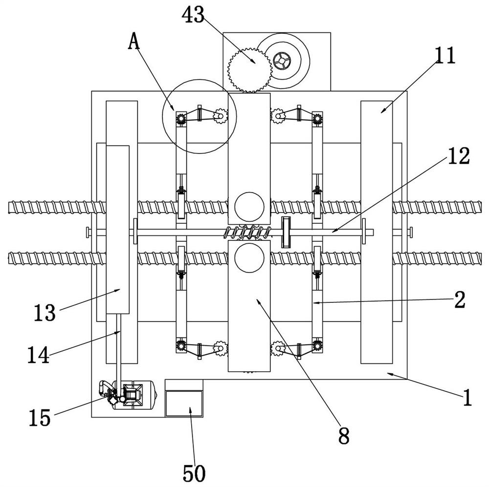
[0052] Embodiment two, on the basis of embodiment one, in order to make better clamping to the experimental object, please refer to figure 1 , image 3 and Figure 10 , Figure 13 , the outer side of the clamping plate 6 is fixed with a second rack 19 along the vertical direction, and the outer side of the second rack 19 is engaged with a first gear 20 which is rotatably matched with the base body 3, and the first gear 20 The lower ends of the lower ends are all meshed with a second worm 21, the second worm 21 is set in rotation with the pull plate 2, and the outer sides of the lower ends of the two rotating columns 7 are provided with a main driving gear 22, and the two main driving gears 22 Both sides are meshed with a second gear 23 set in rotation with the housing 1, and the outer ends of the second worm 21 are coaxially fixed with a bevel gear 24, and the bevel gear 24 is meshed with a pull plate 2 and set in rotation. The second bevel gear 25, the second bevel gear 25...
Embodiment 3
[0055] Embodiment three, on the basis of embodiment one, in order to achieve better clamping of the experimental object, please refer to Figure 10 Since the experimental object is an assembled steel bar, the surface of the steel bar is provided with anti-slip threads, and the upper end of the clamping plate 6 is evenly distributed along the circumference with holes 33 towards the center, and the holes are all slidably fitted with clamping holes. The clamping column 34 in the steel bar thread gap, the upper end of the clamping column 34 is fixedly connected with the clamping plate 6 through the second spring 35;
[0056] When clamping plate 6 moved towards the lower end, because the threads on the surface of the reinforcing bar were distributed in a circular curve, a part of the clamping column 34 could directly contact the reinforcing bar and then be stuck in the thread gap of the reinforcing bar, and a part of the clamping column 34 contacted the anti-slip thread on the surfa...
PUM
 Abstract
Description
Claims
Application Information
 - R&D
- Intellectual Property
- Life Sciences
- Materials
- Tech Scout
- Unparalleled Data Quality
- Higher Quality Content
- 60% Fewer Hallucinations
Browse by: Latest US Patents, China's latest patents, Technical Efficacy Thesaurus, Application Domain, Technology Topic, Popular Technical Reports.
© 2025 PatSnap. All rights reserved.Legal|Privacy policy|Modern Slavery Act Transparency Statement|Sitemap|About US| Contact US: help@patsnap.com


