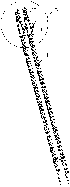
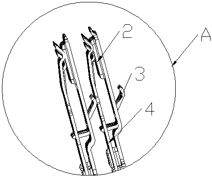
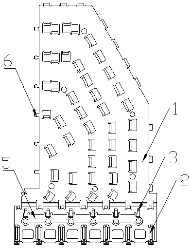
Shielding plate, module structure and electrical connector

A shielding plate and connector technology, which is applied in the direction of connection, parts of the connection device, protective grounding/shielding device of the connection part, etc., can solve the problems of connector crosstalk, achieve the effect of reducing crosstalk, reducing return path, and simple structure

Pending Publication Date: 2019-07-12
SICHUAN HUAFENG ENTERPRISE GRP
View PDF0 Cites 11 Cited by
  • Summary
  • Abstract
  • Description
  • Claims
  • Application Information

AI Technical Summary

Problems solved by technology

[0003] The purpose of the present invention is to provide a shielding plate, a module structu

Method used


Image

  • Shielding plate, module structure and electrical connector
  • Shielding plate, module structure and electrical connector
  • Shielding plate, module structure and electrical connector

Examples


Embodiment Construction

[0028] In order to make the object, technical solution and advantages of the present invention clearer, the present invention will be further described in detail below in conjunction with the accompanying drawings and embodiments. It should be understood that the following detailed description of the embodiments of the invention provided in the accompanying drawings is not intended to limit the scope of the claimed invention, but represents only selected embodiments of the invention. Based on the embodiments of the present invention, all other embodiments obtained by those skilled in the art without making creative efforts belong to the protection scope of the present invention.

[0029] In the description of the present invention, it should be noted that the orientation or positional relationship indicated by the terms "front", "rear", "lower", "upper" etc. is based on the orientation or positional relationship shown in the drawings, or the The usual orientation or positional...


PUM


Abstract

The invention discloses a shielding plate, a conductive end protective sheet, a module structure and an electrical connector. The shielding plate comprises more than two main shielding plates, one ends, connected with the male end of an electrical connector, of the main shielding plates are provided with bulges and first contact terminals; the bulges are configured to be in contact with the male end of the connector, the first contact terminals are configured to butt against the grounding wirings corresponding to the adjacent main shielding plates, two sides of the main shielding plates are respectively provided with the bulges and the first contact terminals, pressure is applied to the grounding wirings corresponding to the adjacent shielding plates through the first contact terminals sothat close contact is formed among the male end of the connector and the bulges and the corresponding grounding wirings, the backflow path is reduced and the crosstalk is reduced.

Description

technical field [0001] The invention relates to the technical field of high-speed backplane connectors, in particular to a shielding plate, a module structure and an electrical connector. Background technique [0002] High-speed connector modules are generally divided into plastic compression modules, base shells, shielding parts, grounding parts, signal parts and auxiliary parts. In order to enhance the shielding effect, the connector will add a shielding plate, and the grounding trace is laid on the shielding plate. When the shielding plate is connected to the grounding piece, as many contact points as possible will be set to reduce the return path and crosstalk. Contents of the invention [0003] The purpose of the present invention is to provide a shielding plate, a module structure and an electrical connector to solve the problem of severe crosstalk in the existing connectors. [0004] In order to solve the above-mentioned technical problems, the present invention ad...

Claims


Application Information

Patent Timeline
IPC IPC(8): H01R13/02H01R13/648H01R13/6581
CPCH01R13/648H01R13/6581H01R13/02
Inventor 邱雪梅贺晓涛
Owner SICHUAN HUAFENG ENTERPRISE GRP
Why Eureka
Try Eureka