Vehicle-mounted magnetic suspension flywheel energy storage system with torsional gyroscopic effect suppression

A flywheel energy storage and gyro effect technology, which is applied in the field of vehicle-mounted flywheel energy storage systems, can solve the problems of high energy consumption, severe torsion gyro effect, and large space occupancy, and achieve low energy consumption, suppression of torsion gyro effect, and cost savings. Effect

Active Publication Date: 2019-07-12
JIANGSU UNIV
View PDF11 Cites 6 Cited by
  • Summary
  • Abstract
  • Description
  • Claims
  • Application Information

AI Technical Summary

Problems solved by technology

[0005] The object of the present invention is to overcome the disadvantages of the existing vehicle-mounted flywheel energy storage system, such as serious torsion gyro effect, large space occupancy rate and high energy consumption, and proposes a vehicle-mounted magnetic levitation flywheel energy storage system that can suppress the torsion gyro effect. From the structure It realizes the suppression of the torsion gyro effect, reduces the space occupancy rate, improves the integration level, and reduces the energy consumption

Method used


Image

  • Vehicle-mounted magnetic suspension flywheel energy storage system with torsional gyroscopic effect suppression
  • Vehicle-mounted magnetic suspension flywheel energy storage system with torsional gyroscopic effect suppression
  • Vehicle-mounted magnetic suspension flywheel energy storage system with torsional gyroscopic effect suppression

Examples


Embodiment Construction

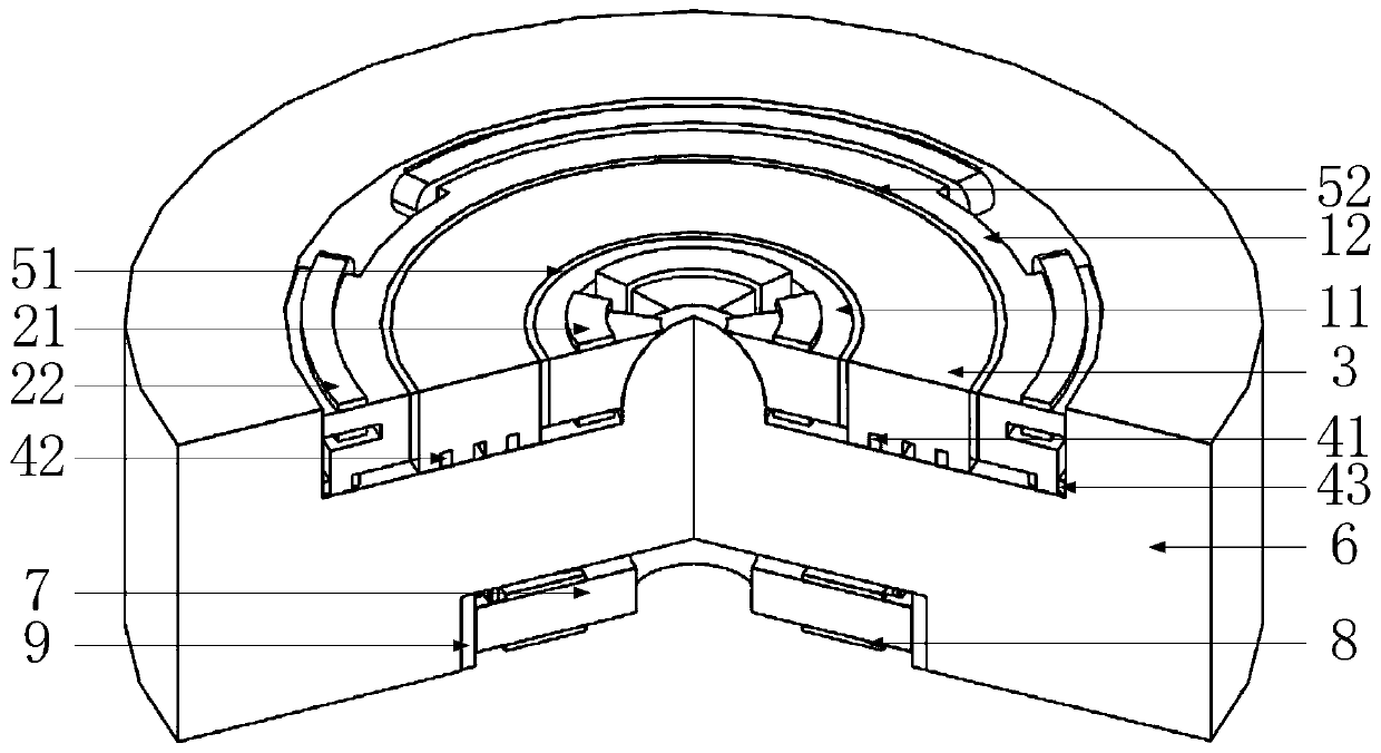
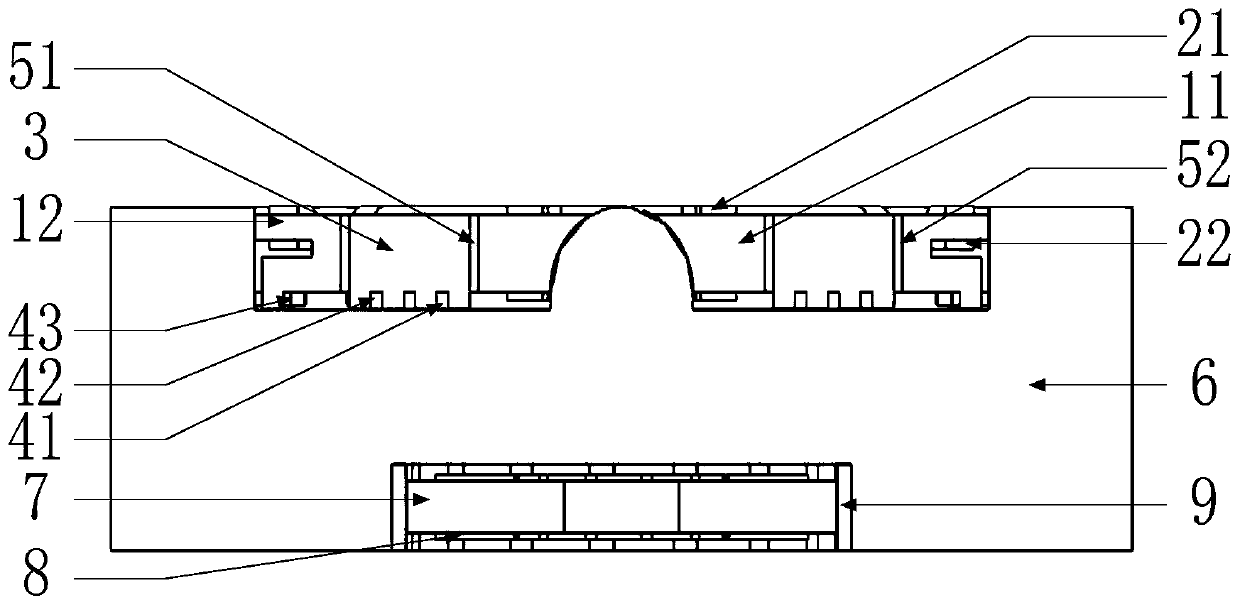
[0041] see figure 1 with figure 2 As shown, the present invention includes a five-degree-of-freedom magnetic bearing arranged coaxially, a flywheel rotor 6 and an outer rotor motor. The five-degree-of-freedom magnetic bearing includes a radial inner stator 11 , a radial outer stator 12 , and an axial stator 4 ; the outer rotor motor includes a motor stator 7 , a motor coil 8 , and a permanent magnet 9 . The five-degree-of-freedom magnetic bearing is fixedly embedded in the upper section of the flywheel rotor 6 , and the outer rotor motor is embedded in the lower section of the flywheel rotor 6 .

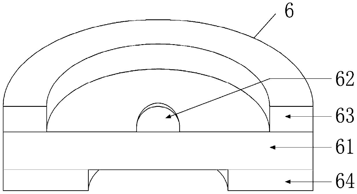
[0042] see image 3 As shown in the structure of the flywheel rotor 6, the flywheel rotor 6 is a cylindrical structure as a whole, which is composed of a flywheel rotor main cylinder 61, an inner receiving pole 62, an upper ring 63 and a lower ring 64 assembled on the same axis. The main cylinder 61 of the flywheel rotor is a cylinder, and the middle section of the flywheel rotor...


PUM


Abstract

The invention discloses a vehicle-mounted magnetic suspension flywheel energy storage system with a torsional gyroscopic effect suppression. The system comprises a five-degree-of-freedom magnetic bearing, a flywheel rotor and an outer rotor motor which are coaxially arranged, wherein the middle section of the flywheel rotor is a flywheel rotor main cylinder, the lower section is a lower end circular ring, the external part of the upper section of the flywheel rotor is an upper end circular ring, the middle of the upper section is an inner receiving pole, the lower section is a lower end circular ring, the inner receiving pole is of a hemispherical structure, the inner diameter of the upper end circular ring is greater than the inner diameter of the lower end circular ring, the diameter ofthe inner receiving pole is less than the inner diameter of the lower end circular ring, a circular ring-like groove is formed among the flywheel rotor main cylinder, the inner receiving pole and theupper end circular ring, the five-degree-of-freedom magnetic bearing is arranged in the circular ring-like groove, a cylindrical groove is formed between the flywheel main cylinder and the lower end circular ring, and the outer rotor motor is arranged in the cylindrical groove. The system is supported by adopting the unilateral highly integrated five-degree-of-freedom magnetic bearing, which reduces the axial size and suppresses the torsional gyroscopic effect.

Description

technical field [0001] The invention relates to a vehicle-mounted flywheel energy storage system (also called a flywheel battery) for electric vehicles, especially suitable for electric vehicles on steep slopes, undulating roads, muddy roads and other road conditions where the torsional gyro effect is severe, and can strongly suppress the torsion gyro effect. Background technique [0002] Flywheel battery is a kind of mechanical energy storage battery, which has the advantages of high charging efficiency, high power, small mass, no pollution and long life, and is used as an ideal power battery for electric vehicles. However, when the vehicle-mounted flywheel battery is applied to road conditions with severe torsional gyro effect, such as up and down steep slopes, undulating roads, muddy roads, etc., there are problems such as severe torsional gyro effect and large space occupancy. [0003] Current magnetic bearings usually use axial single-degree-of-freedom magnetic bearings...

Claims


Application Information

Patent Timeline
Patent Type & Authority Applications(China)
IPC IPC(8): H02K7/02
CPCH02K7/025Y02E60/16
Inventor 张维煜王健萍程烨东杨启富朱鹏飞张林东李凯张松
Owner JIANGSU UNIV
Why Eureka
Try Eureka