
High speed brushless DC permanent magnet motor for vacuum cleaner

A technology for permanent magnet motors and vacuum cleaners, which is applied to electric components, magnetic circuits, electromechanical devices, etc., can solve the problem of increasing the cost of the motor body structure and drive controller, the inability of the permanent magnet motor to reach a high speed, and affecting the suction effect and durability of the vacuum cleaner. It can reduce the failure rate, the stress condition is uniform and good, and the resonance phenomenon can be avoided.

Active Publication Date: 2019-10-25
ONCE TOP MOTOR MFG
View PDF4 Cites 0 Cited by
  • Summary
  • Abstract
  • Description
  • Claims
  • Application Information

AI Technical Summary

Problems solved by technology

[0003] Therefore, it has become a top priority to provide high-quality power sources for household vacuum cleaners. At present, the permanent magnet motors of vacuum cleaners still have the following deficiencies: (1) Some permanent magnet motors of vacuum cleaners still use a brush structure, which limits the speed and life of the motor, thereby affecting The suction effect and durability of the vacuum cleaner; (2) The brushless DC permanent magnet motor vacuum cleaner with multi-slot and multi-pole structure not only has higher requirements for motor processing and manufacturing, but also requires a high electronic commutation frequency, which makes the motor body structure and drive The cost of the controller increases; (3) The speed of the permanent magnet motor cannot reach a high level, which makes the dust collection effect of the vacuum cleaner poor; (4) The vibration and noise of the permanent magnet motor are too large, which reduces the satisfaction of consumers using the vacuum cleaner Spend

Method used


Image

  • High speed brushless DC permanent magnet motor for vacuum cleaner
  • High speed brushless DC permanent magnet motor for vacuum cleaner
  • High speed brushless DC permanent magnet motor for vacuum cleaner

Examples


Embodiment Construction

[0031] In order to make the purpose, technical solutions and advantages of the embodiments of the present invention clearer, the technical solutions in the embodiments of the present invention will be clearly and completely described below in conjunction with the drawings in the embodiments of the present invention. Obviously, the described embodiments It is a part of embodiments of the present invention, but not all embodiments. The components of the embodiments of the invention generally described and illustrated in the figures herein may be arranged and designed in a variety of different configurations. Accordingly, the following detailed description of the embodiments of the invention provided in the accompanying drawings is not intended to limit the scope of the claimed invention, but merely represents selected embodiments of the invention. Based on the embodiments of the present invention, all other embodiments obtained by persons of ordinary skill in the art without cre...


PUM


Abstract

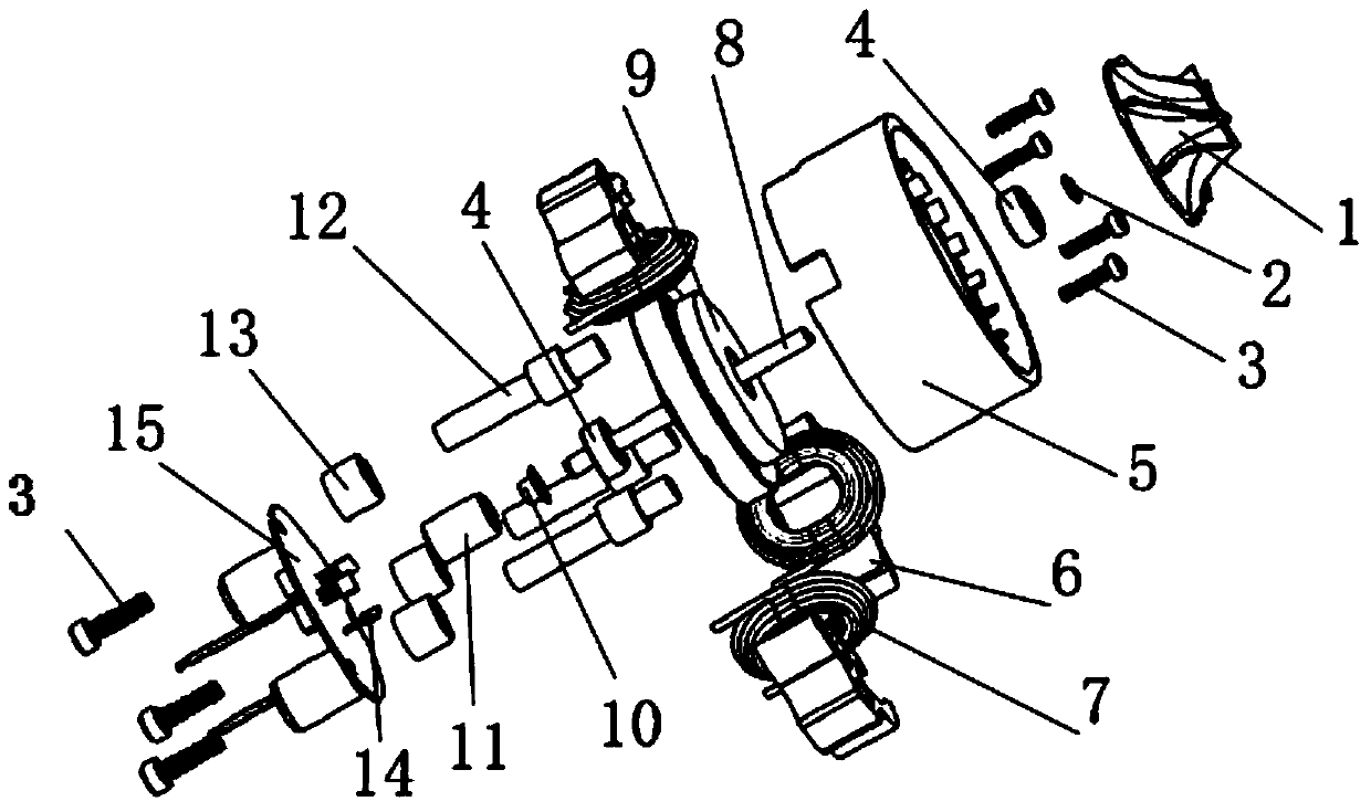
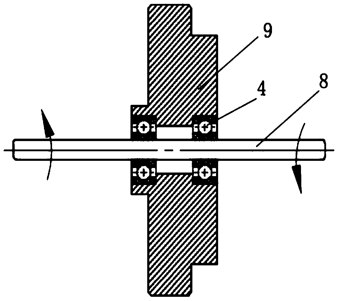
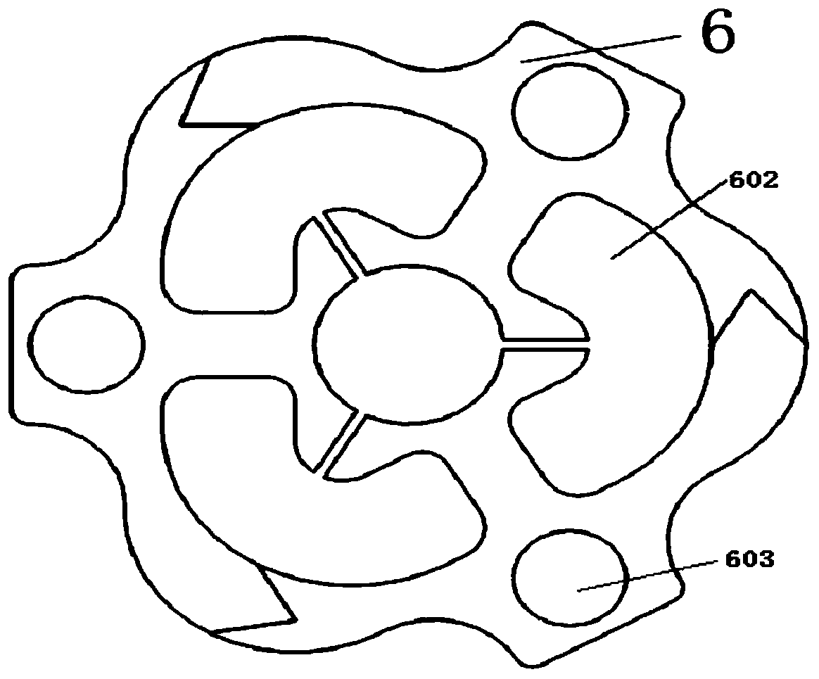
The invention discloses a vacuum cleaner high-speed brushless DC permanent magnet motor comprising a shafting assembly, a stator assembly, and a drive controller. The shafting assembly comprises a rotating shaft, bearings, blades, and a magnet. The stator assembly comprises a stator, armature windings, a guide bar, and a motor base connected with the guide bar. The rotating shaft is connected with the motor base through the bearings. The magnet is installed at one side, near the stator, of the rotating shaft, and the blades are installed at the other side. The stator is formed by splicing armature tooth blocks, and is provided with stator slots and positioning holes. The stator slot of each armature tooth winds the corresponding armature winding. The stator is connected through the positioning holes with the guide bar for and is thus fixed. The stator is formed by splicing and combining more than three armature teeth. The motor base is provided with a center hole which is internally equipped with a bearing chamber in which the bearings are arranged. The motor base is connected with the rotating shaft through the bearings.

Description

technical field [0001] The invention relates to the technical field of permanent magnet direct current motors, in particular to a brushless direct current permanent magnet motor in the field of household appliances. Background technique [0002] Brushless DC permanent magnet motors are widely used because of their compact structure, long life, high efficiency, stable operation and various structural forms. With the continuous improvement of people's living standards and the needs of energy conservation and environmental protection, brushless DC permanent magnet motors The market demand for household appliances as a power source is increasing, especially high-quality household appliances represented by vacuum cleaners are being favored by more and more consumers. [0003] Therefore, it has become a top priority to provide high-quality power sources for household vacuum cleaners. At present, the permanent magnet motors of vacuum cleaners still have the following deficiencies: ...

Claims


Application Information

Patent Timeline
Patent Type & Authority Patents(China)
IPC IPC(8): H02K29/00H02K9/06H02K5/16H02K1/16H02K11/30H02K1/18H02K29/08
CPCH02K1/165H02K1/185H02K5/161H02K9/06H02K29/00H02K29/08
Inventor 张用万
Owner ONCE TOP MOTOR MFG
Learn More