
Thin-wall shell forming die device with rigid insertion type solid core male die

A thin-walled shell, plug-in technology, used in household components, household appliances, other household appliances, etc., can solve the problems of inaccurate positioning, reduced pressure resistance, inconsistent wall thickness of helmets, etc., to improve production quality and Efficiency, reduce the probability of deviation, and ensure the effect of wall thickness uniformity

Pending Publication Date: 2019-07-16
厦门宇诠复材科技有限公司
View PDF0 Cites 3 Cited by
  • Summary
  • Abstract
  • Description
  • Claims
  • Application Information

AI Technical Summary

Problems solved by technology

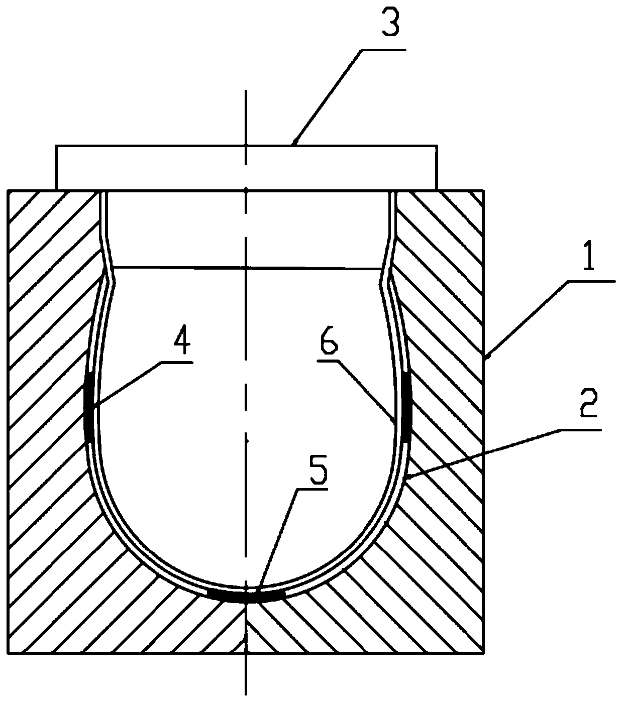
[0004] This kind of molding equipment has the following disadvantages: 1. Since the male mold bag is a soft and thin-walled bag body structure, the hot water or hot oil filled into the male mold bag is prone to glue accumulation on the inside under the action of gravity, causing safety hazards. A very thin top deformation layer 5 is formed on the top of the cap, while a thicker side deformation layer 4 is formed on both sides, resulting in inconsistent wall thickness of the helmet, resulting in reduced compression resistance and easy damage
2. Since the composite fiber material needs to be stacked in small pieces next to the inner wall of the female mold 1 before being put into the male mold bag 6, when the male mold bag 6 enters, due to the impact of the male mold bag 6 Inhomogeneity causes the composite fiber material to be easily shifted, resulting in inaccurate positioning, which reduces the molding rate of the helmet and deteriorates the molding quality
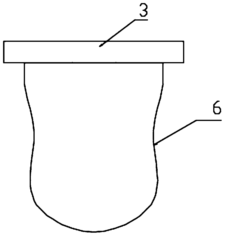
3. When the male mold bag is filled with hot air, the protruding part of the male mold bag's outer wall will be formed thinner, while the concave part will be formed thicker, resulting in a deviation in the size of the molded part

Method used


Image

  • Thin-wall shell forming die device with rigid insertion type solid core male die
  • Thin-wall shell forming die device with rigid insertion type solid core male die
  • Thin-wall shell forming die device with rigid insertion type solid core male die

Examples


Embodiment Construction

[0030] In order to enable those skilled in the art to better understand the technical solution of the present invention, the present invention will be described in detail below in conjunction with the accompanying drawings. The description in this part is only exemplary and explanatory, and should not have any limiting effect on the protection scope of the present invention. .

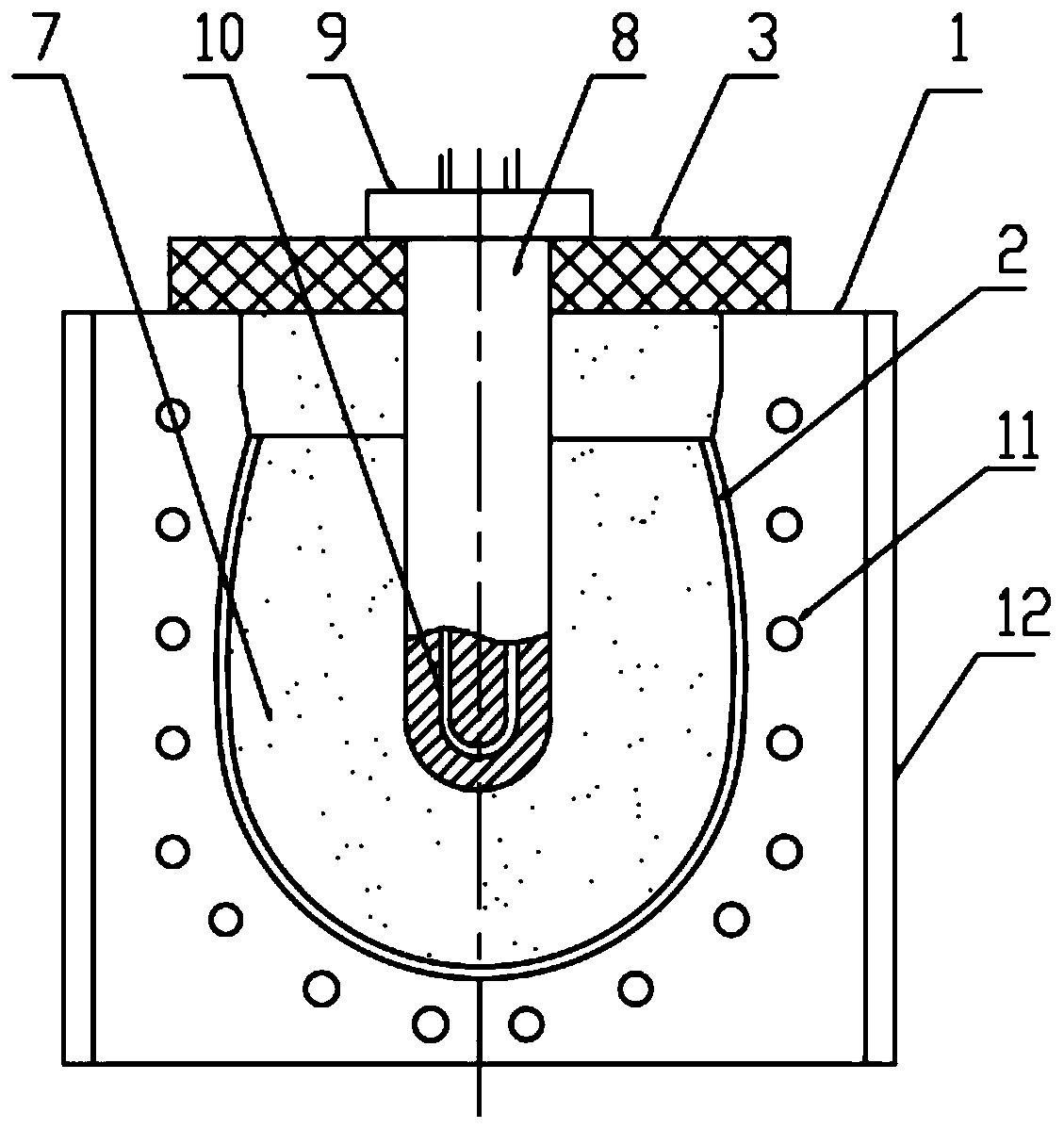
[0031] Such as Figure 3-Figure 9 Shown, the concrete structure of the present invention is:

[0032] A thin-walled shell molding die device with a rigid plug-in solid core male mold, which includes a female mold 1 that is at least divided into two facing parts, and a male mold 7 is arranged in the female mold 1; the outer wall of the male mold 7 is in contact with the A cavity for forming the shell is formed between the inner walls of the female mold 1; the male mold 7 is a solid silicone structure; the male mold 7 is provided with a core for inserting the mandrel 8 and matching the shape of the mand...


PUM


Abstract

The invention discloses a thin-wall shell forming die device with a rigid insertion type solid core male die. The thin-wall shell forming die device comprises a female die which is divided into at least two oppositely-arranged parts, and the male die is arranged in the female die; a cavity for forming a shell is formed between the outer wall of the male die and the inner wall of the female die; the male mold is of a solid-core silica gel structure; a core shaft hole which is used for being inserted into by a core shaft and is matched with the core shaft in shape is formed in the male mold; anda core shaft hole port is located at the tail end of the male mold. The thin-wall shell forming die device with the rigid insertion type solid core male die can eliminate glue accumulation, ensure uniform wall thickness of the formed shell, and is more convenient and fast to operate.

Description

technical field [0001] The invention relates to the field of processing equipment for shell parts, in particular to a thin-walled shell forming die device with a rigid plug-in solid core male die. Background technique [0002] Existing helmet shells, such as various motorcycle or racing helmets, engineering helmets, etc., are generally made of lightweight materials for ergonomics and comfort, and the lightweight materials are reinforced with composite fiber materials, especially fibers. The thermoplastic matrix material is mainly used. When processing thermoplastic composite fiber materials into helmet shells, it is common to arrange multiple portions of fiber-reinforced LFRTP fabric on helmet shell forming equipment to form overlapping layers, heat the multilayer structure, and Pressure is applied under vacuum for a certain period of time, and then cooling is performed to a temperature that allows demoulding. [0003] Existing molding equipment mainly includes a female mo...

Claims


Application Information

Patent Timeline
Patent Type & Authority Applications(China)
IPC IPC(8): B29C70/46B29C33/02B29C33/04B29L31/48
CPCB29C70/46B29C33/02B29C33/04B29L2031/4821B29L2031/4814
Inventor 徐守志陈意升陈旗首黄远峰
Owner 厦门宇诠复材科技有限公司
Learn More