Eureka AIR delivers breakthrough ideas for toughest innovation challenges, trusted by R&D personnel around the world.

Ultrasonic motor testing device based on LabVIEW virtual instrument platform

An ultrasonic motor and virtual instrument technology, which is applied in motor generator testing, machine/structural component testing, measuring devices, etc., can solve the problem of complex driving control circuits, limiting the application range of longitudinal-bending composite ultrasonic motors, and the difficulty of ultrasonic motors. Miniaturization and other issues, to achieve the effect of good development potential and significance

Inactive Publication Date: 2019-07-16
HEILONGJIANG INST OF TECH
View PDF1 Cites 4 Cited by
  • Summary
  • Abstract
  • Description
  • Claims
  • Application Information

AI Technical Summary

Problems solved by technology

[0006] 2. Research on intelligentization and integration of drive control circuits
[0007] The drive control circuit is complex, which is a problem that must be solved to realize the industrialization of ultrasonic motors. Only by realizing the intelligence and integration of the motor drive control circuit can the operating performance be improved, the system volume reduced and the cost of the product reduced. Only in this way can it be realized Scale Production of Ultrasonic Motors
[0008] 3. Research on miniaturization
[0009] At this stage, ultrasonic motors are usually sandwich structures, and the radial dimension is difficult to reduce, which makes it difficult to miniaturize ultrasonic motors
This problem limits the application range of the longitudinal bending composite ultrasonic motor, so it is necessary to design a new structure and new principle of the longitudinal bending composite ultrasonic motor to make it easy to miniaturize and expand its application field

Method used


Image

  • Ultrasonic motor testing device based on LabVIEW virtual instrument platform
  • Ultrasonic motor testing device based on LabVIEW virtual instrument platform
  • Ultrasonic motor testing device based on LabVIEW virtual instrument platform

Examples


Embodiment Construction

[0033] The technical solution of the present invention will be further described below in conjunction with the accompanying drawings, but it is not limited thereto. Any modification or equivalent replacement of the technical solution of the present invention without departing from the spirit and scope of the technical solution of the present invention should be covered by the present invention. within the scope of protection.

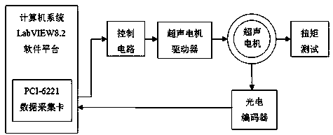
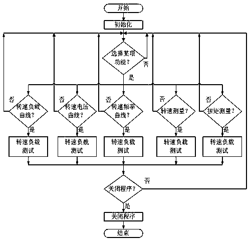
[0034] The present invention provides a kind of ultrasonic motor testing device based on LabVIEW virtual instrument platform, and it comprises two parts of testing device hardware composition and software design, and specific content is as follows:

[0035] 1. The hardware composition of the test device

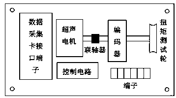
[0036] The hardware composition and plane layout of the ultrasonic motor testing device are as follows: figure 1 and figure 2 shown. The whole platform is mainly composed of computer system, control circuit, ultrasonic motor, ultrasonic motor drive...


PUM


Abstract

The invention discloses an ultrasonic motor testing device based on a LabVIEW virtual instrument platform. The device comprises a computer system, a control circuit, an ultrasonic motor, an ultrasonicmotor driver, a photoelectric encoder and a torque testing device, wherein the computer system comprises a LabVIEW virtual instrument software design platform and a data collection card; the data collection card is used for controlling signal output and the collection of a photoelectric encoder feedback signal; the LabVIEW virtual instrument platform is used for inputting control parameters and displaying test results; the control motor is used for converting a control signal emitted from the data collection card into a control signal which can be identified by an ultrasonic motor controller;the ultrasonic motor driver is used for driving the ultrasonic motor to rotate; the photoelectric encoder is used for converting the revolving speed of the ultrasonic motor into an electric pulse signal; and the torque testing device is used for measuring the output torque of the ultrasonic motor. A measurement result is compared with the measurement result of a discrete instrument, and the measurement result is basically the same.

Description

technical field [0001] The invention relates to an ultrasonic motor testing device. Background technique [0002] In the application fields of direct drive, precision drive and non-magnetic drive, such as aerial antenna horns for signal tracking in millimeter wave communication systems, joint drives, high-precision positioning pan-tilts, etc., the drive motors need to have fast response and large output torque. And features such as low energy consumption locking. At present, the driving method of electromagnetic motor acceleration and deceleration is used. The decelerator has shortcomings such as return stroke and transmission error, flexibility, nonlinear friction and low damping. These shortcomings will affect the stability of the frame servo system and reduce the accuracy of the system output speed and position. ; The electromagnetic motor itself does not have self-locking characteristics, and the realization of locking is often accompanied by energy consumption and comp...

Claims


Application Information

Patent Timeline
Patent Type & Authority Applications(China)
IPC IPC(8): G01R31/34G01M15/00
CPCG01M15/00G01R31/34
Inventor 宋起超杨春光
Owner HEILONGJIANG INST OF TECH
Why Eureka
Eureka Blog
Learn More