Surgical instrument cleaning device for hepatobiliary surgery department
A technique for surgical instruments and cleaning devices, applied in the field of surgical instrument cleaning devices for hepatobiliary surgery, can solve problems such as incomplete cleaning of surgical instruments and cross-infection, and achieve the effect of being convenient for storage and secondary use, and avoiding incomplete cleaning.
- Summary
- Abstract
- Description
- Claims
- Application Information
AI Technical Summary
Problems solved by technology
Method used
Image
Examples
Embodiment 1
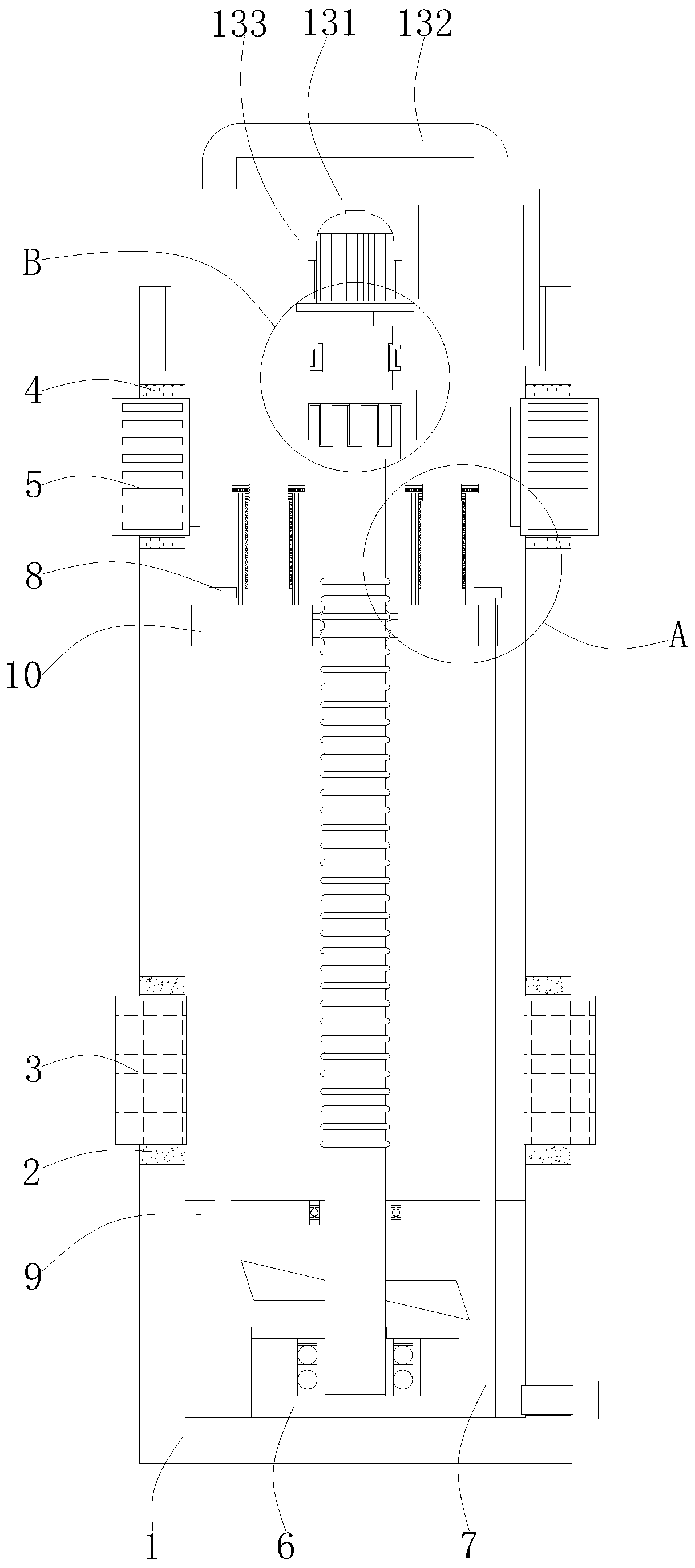
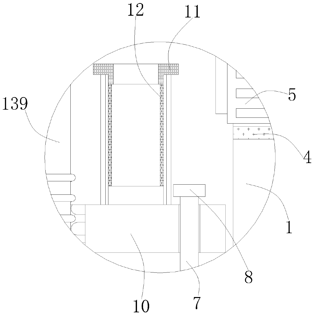
[0027] Such as Figure 1-3 As shown, a surgical instrument cleaning device for hepatobiliary surgery includes a cleaning cylinder 1, a sealing ring 2, an acoustic wave transmitter 3, a fixing ring 4, a dryer 5, a support table 6, a guide rod 7, a sealing cap 8, and a limit rod 9. Bearing platform 10, support frame 11, partition net 12, lifting mechanism 13, the number of sealing rings 2 is two, and the two sealing rings 2 are symmetrically arranged at the bottom of the left and right sides of cleaning cylinder 1, the number of acoustic wave transmitters 3 There are two sound wave emitters 3 respectively arranged in the middle of the opposite sides of the two sealing rings 2, the number of the fixing rings 4 is two, and the two fixing rings 4 are symmetrically arranged on the tops of the left and right sides of the cleaning cylinder 1 , the number of dryers 5 is two, and the two dryers 5 are respectively arranged in the middle of the opposite sides of the two fixed rings 4 .
...
Embodiment 2
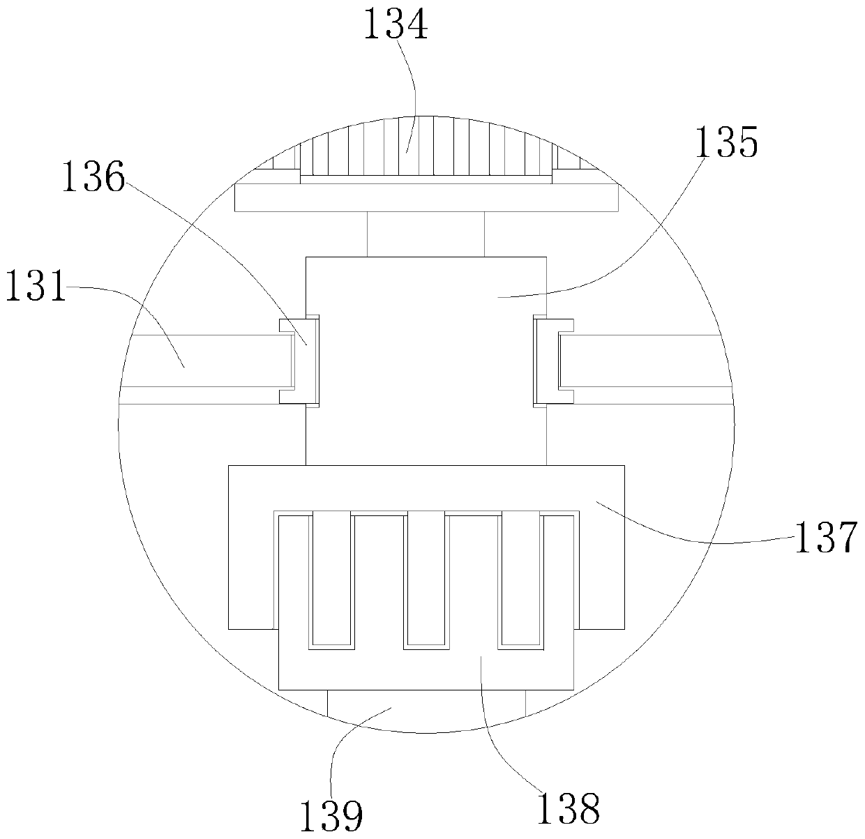
[0030] On the basis of Embodiment 1, the lifting mechanism 13 includes a load-bearing box 131, a handle 132, a fixed frame 133, a motor 134, a rotating shaft 135, an I-shaped limit ring 136, a connecting sleeve 137, a connecting block 138, and a transmission shaft 139. The handle 132 is fixedly connected to the center of the top of the load-bearing box 131 , the top of the fixed frame 133 is fixedly connected to the center of the top of the inner wall of the force-bearing box 131 , and the fixed frame 133 is sleeved on the outside of the motor 134 .
Embodiment 3
[0032] On the basis of Embodiments 1 and 2, the rotating shaft 135 is arranged at the center of the bottom of the bearing box 131, the I-shaped stop ring 136 is arranged at the center of the bottom of the bearing box 131, and one end of the rotating shaft 135 bottom is fixedly connected to the In the middle of the top of the connecting sleeve 137 , the connecting block 138 is arranged in the middle of the bottom of the bearing box 131 , and one end of the top of the transmission shaft 139 is fixedly connected in the middle of the bottom of the connecting block 138 .
PUM
 Abstract
Description
Claims
Application Information
 - R&D
- Intellectual Property
- Life Sciences
- Materials
- Tech Scout
- Unparalleled Data Quality
- Higher Quality Content
- 60% Fewer Hallucinations
Browse by: Latest US Patents, China's latest patents, Technical Efficacy Thesaurus, Application Domain, Technology Topic, Popular Technical Reports.
© 2025 PatSnap. All rights reserved.Legal|Privacy policy|Modern Slavery Act Transparency Statement|Sitemap|About US| Contact US: help@patsnap.com


