Stirring friction extrusion method and device based on stirring needle
A friction stir and extrusion device technology, applied in ceramic extrusion dies, ceramic molding machines, manufacturing tools, etc., can solve the problems of composition segregation, separation of reinforcing phase and matrix metal and grain growth, and achieve stable structure and performance. Effect
- Summary
- Abstract
- Description
- Claims
- Application Information
AI Technical Summary
Problems solved by technology
Method used
Image

Examples
Embodiment 1
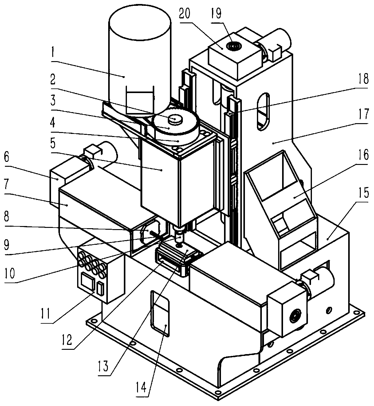
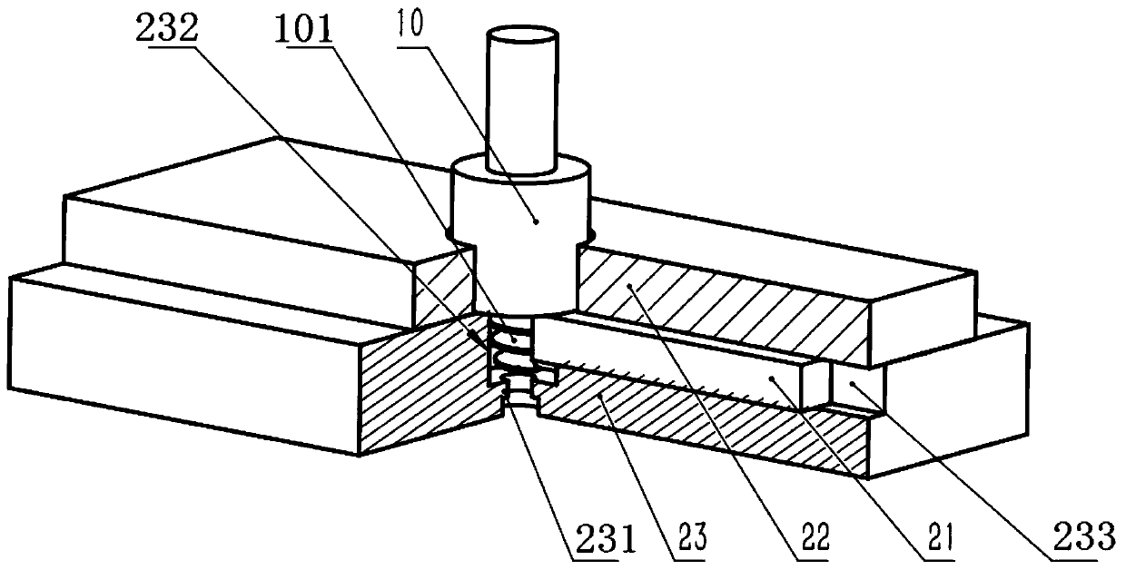
[0043] Such as figure 1As shown, the friction stirring extrusion device based on the stirring pin 101 in this embodiment includes a base 15, on which a mold 23 assembly 13, an extruding assembly and a lifting assembly are arranged, and the mold 23 assembly 13 includes a mold 23 and is arranged on the mold 23. The cover plate 22, the mold 23 and the anvil 12 are connected by fasteners, and the anvil 12 and the base 15 are connected by fasteners. A feeding trough is provided between the mold 23 and the cover plate 22, and a prefabricated body 21, the cover plate 22 is provided with a through hole communicating with the mold stirring area 232, the feeding trough communicates with the mold stirring area 232, the base 15 is provided with a cavity corresponding to the mold outlet 231 at the bottom of the mold 23, and the side wall of the cavity is provided with There is a viewing window 14; the extruding assembly includes a box body 7, a horizontal first screw mandrel arranged in th...
Embodiment 2
[0051] Such as Figure 5 As shown, this embodiment provides a friction stir extrusion device based on the stirring needle 101. On the basis of the first embodiment, the friction stir extrusion device based on the stirring needle 101 in this embodiment also has the following characteristics: the mold 23 is The polygonal mold 2423 is provided with multiple groups of feed grooves. Each set includes two slots. Multiple sets of different materials can be mixed simultaneously during extrusion. In the specific operation process, according to the properties of the required materials, the materials in the grooves of the mold 23 can be mixed and extruded in stages. For example, materials with different functions are placed in the first feed tank 241 , the second feed tank 242 , and the third feed tank 243 , and materials with different functions can be obtained according to the order of feeding. For example, one functional material can be obtained according to the feeding sequence of...
Embodiment 3
[0053] Such as Figure 6-10 As shown, this embodiment provides a friction stir extrusion device based on the stirring needle 101. On the basis of the first embodiment, the friction stir extrusion device based on the stirring needle 101 in this embodiment also has the following characteristics: the mold 23 adopts Split mold 26, so that when the size of the stirring hole in the mold stirring zone 232 meets the requirements; The split mold 26 and the mold 23 support 17 are a transition fit, and the feed groove of the split mold 26 is slightly larger than the feed groove of the mold 23 support 17. Figure 7 It is a schematic diagram of the three-dimensional structure of the split mold 26 in the present invention. Such as Figure 8-10 As shown, the shape of the split die outlet 261 is circular, and may also be square or flower-shaped, and different cross-sectional shapes can meet the special requirements of different extrusion materials on the cross-section.
PUM
 Abstract
Description
Claims
Application Information
 - R&D
- Intellectual Property
- Life Sciences
- Materials
- Tech Scout
- Unparalleled Data Quality
- Higher Quality Content
- 60% Fewer Hallucinations
Browse by: Latest US Patents, China's latest patents, Technical Efficacy Thesaurus, Application Domain, Technology Topic, Popular Technical Reports.
© 2025 PatSnap. All rights reserved.Legal|Privacy policy|Modern Slavery Act Transparency Statement|Sitemap|About US| Contact US: help@patsnap.com