
System and method for online detecting service life of polishing pad

A polishing pad and life technology, which is applied in grinding/polishing equipment, parts of grinding machine tools, control of workpiece feed movement, etc., can solve the problem of inconsistent polishing pad wear, product yield and yield decline, and production efficiency. and other problems, to achieve the effect of improving the quality of flattening, making full use of it, and making small changes.

Inactive Publication Date: 2019-07-19
HANGZHOU ZHONGGUI ELECTRONICS TECH CO LTD
View PDF11 Cites 9 Cited by
  • Summary
  • Abstract
  • Description
  • Claims
  • Application Information

AI Technical Summary

Problems solved by technology

[0009] Among them, the disadvantage of methods 1 and 2 is that, due to fluctuations in parameters such as the speed of the polishing table, the speed of the polishing head, the flow rate of the polishing liquid, and the temperature, it is easy to cause the wear of the polishing pad under the same working time or the same number of planarized wafers Inconsistency, replacing the polishing pad too early will easily cause waste, and replacing the polishing pad too late will easily lead to a decrease in product yield and yield
The disadvantage of method 3 is that it is necessary to manually measure the groove depth of the polishing pad, which will cause contamination of the polishing pad and reduce production efficiency

Method used


Image

  • System and method for online detecting service life of polishing pad
  • System and method for online detecting service life of polishing pad
  • System and method for online detecting service life of polishing pad

Examples


Embodiment Construction

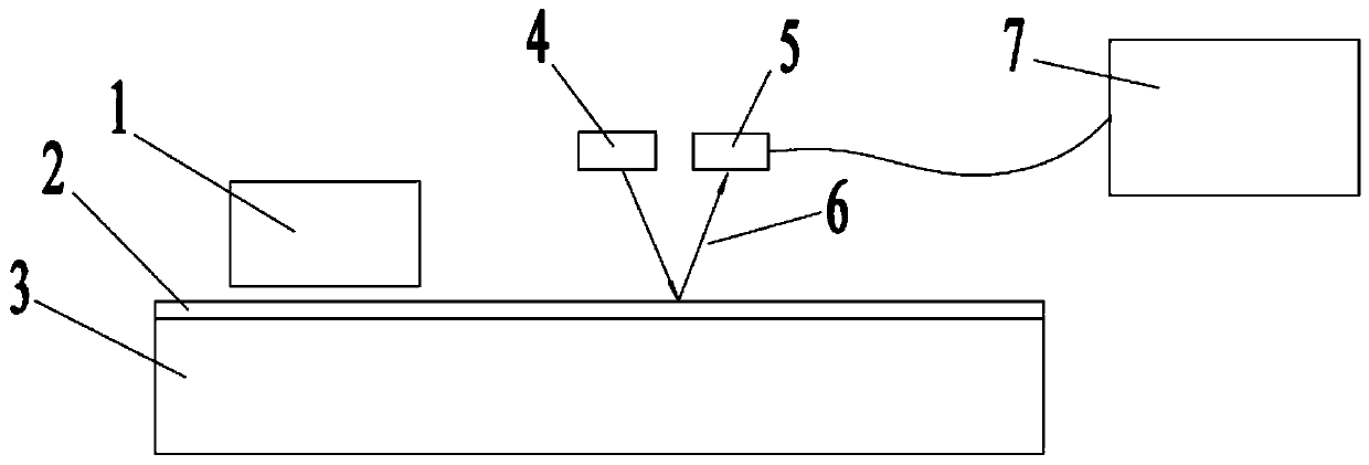
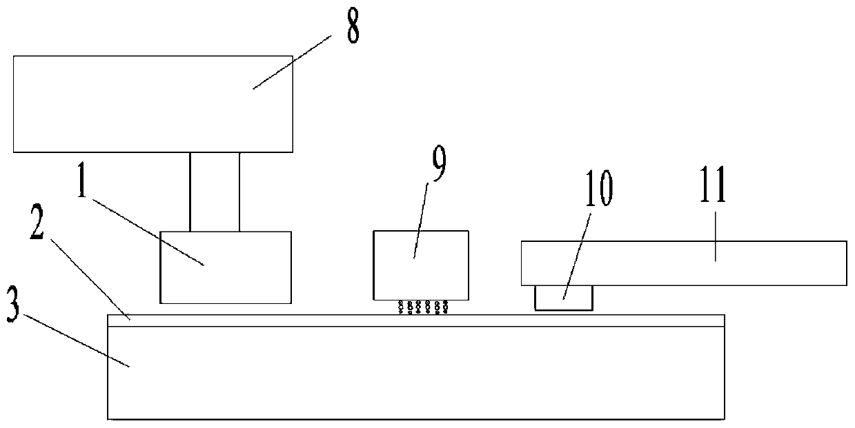
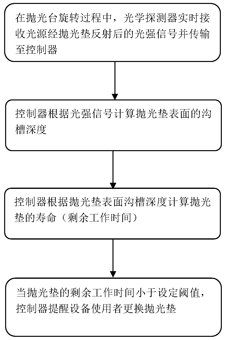
[0041] refer to figure 1 and figure 2 Shown, provide an embodiment of the online detection system of polishing pad life:

[0042] The system includes a polishing table 3 , the polishing pad 2 with grooves is pasted on the upper surface of the polishing table 3 and rotates together with the polishing table 3 . A light source 4 and an optical detector 5 are arranged above the polishing area. The light source 4 emits a light beam 6 to the surface of the polishing pad 2 and is reflected to the optical detector 5 by the surface of the polishing pad 2 .

[0043] The light source 4 and the optical detector 5 may be an integrated photoelectric sensor; or, the light source 4 and the optical detector 5 may be independent components.

[0044] A polishing head 1 carrying a wafer is arranged above the polishing table 3 , and the light source 4 and the optical detector 5 can be installed on a polishing arm 8 that fixes the polishing head 1 .

[0045] A nozzle for supplying polishing liq...


PUM


Abstract

The invention relates to a system and method for online detecting of service life of a polishing pad. According to the system and the method, the polishing pad with a groove is arranged on the surfaceof a polishing table and rotates along with the polishing table; a polishing head presses a wafer on the surface of the polishing pad and moves relative to the polishing table to flatten the wafer, specifically, a component corresponding to the polishing area is provided with a light source and an optical detector, and the light source emits light beams to the surface of the polishing pad and reflects the light beams to the optical detector; and a controller receives a signal from the optical detector on line, calculates the depth of the groove according to the strength of the signal, and judges the residual working time of the polishing pad. The invention also provides a CMP process parameter on-line adjusting method based on the service life detecting of the polishing pad, wherein the CMP process parameter, such as the planarization time, is adjusted on-line according to the residual working time of the polishing pad. The factors such as the rotation speed of the polishing table, the rotation speed of the polishing head, the pressure of the polishing head, the flow of polishing liquid and the temperature of the polishing disc can control the wafer planarization removal efficiency, so that the planarization efficiency and the planarization quality of the wafer are improved.

Description

technical field [0001] The invention relates to the field of equipment for manufacturing semiconductor integrated circuit chips, in particular to a system and method for online detection of the life of a polishing pad. Background technique [0002] Chemical mechanical planarization (Chemical Mechanical Planarization, CMP) is a process technology capable of achieving global and local planarization of semiconductor elements (such as wafers). [0003] The CMP equipment includes a polishing table, the surface of the polishing table is provided with a polishing pad; above the polishing table, a polishing head is provided to clamp the wafer to be processed, and a certain pressure is applied to press the wafer tightly against the surface of the polishing pad. surface; the polishing head and the polishing table move or rotate relative to each other, and at the same time, the polishing liquid composed of abrasive grains and chemical solution flows between the wafer and the polishing ...

Claims


Application Information

Patent Timeline
Patent Type & Authority Applications(China)
IPC IPC(8): B24B37/005B24B37/10B24B49/12B24B57/02B24B53/017
CPCB24B37/0053B24B37/10B24B49/12B24B53/017B24B57/02
Inventor 顾静然林胜强
Owner HANGZHOU ZHONGGUI ELECTRONICS TECH CO LTD
Learn More