Bionic joint control system and method based on multi-motor drive

A multi-motor-driven, bionic joint technology, applied in the direction of program control manipulators, manipulators, manufacturing tools, etc., can solve the problems of poor system robustness, high cost in high torque scenarios, slow response curves, etc., and achieve control flexibility. Poor, improve robustness reliability, solve the effect of poor variable stiffness performance

Active Publication Date: 2019-07-19
深圳市智能机器人研究院
View PDF6 Cites 5 Cited by
  • Summary
  • Abstract
  • Description
  • Claims
  • Application Information

AI Technical Summary

Problems solved by technology

[0003] For flexible robots with passive and flexible control, it is necessary to add elastic devices to the hardware, and the elastic devices are large in size and complex in structure. Flexible robots with active flexible control face problems such as poor variable stiffness performance, poor system robustness, poor control flexibility, and high cost in high-torque scenarios, and a single high-torque motor weighs a lot, the response curve is slow, and the control accuracy is not high.

Method used


Image

  • Bionic joint control system and method based on multi-motor drive
  • Bionic joint control system and method based on multi-motor drive
  • Bionic joint control system and method based on multi-motor drive

Examples


Embodiment 1

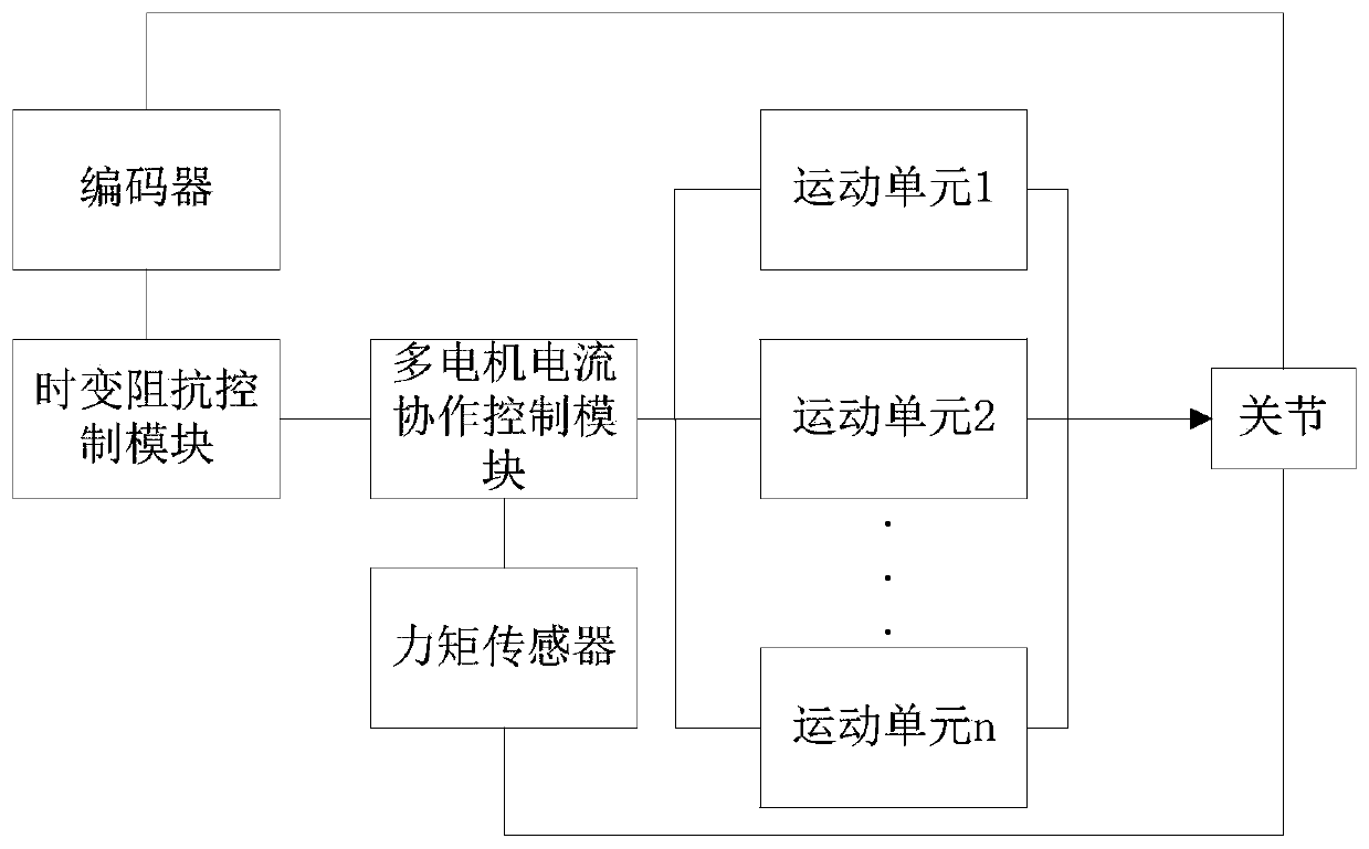
[0043] Such as figure 1 As shown, this embodiment provides a bionic joint control system based on multi-motor drive, including a time-varying impedance control module, a multi-motor current cooperative control module, an encoder, a torque sensor and a plurality of motion units, the plurality of motion units Acting in parallel on the joints, each of the motion units includes a motor and a driver, the time-varying impedance control module is connected to the encoder and the multi-motor current cooperative control module, and the multi-motor current cooperative control module is connected to the torque sensor and each driver respectively connect;

[0044] The encoder is used to obtain the angle information of the joint, and transmit the angle information to the time-varying impedance control module;

[0045] The torque sensor is used to obtain the torque information of the joint, and transmit the torque information to the multi-motor current cooperative control module;

[0046]...

Embodiment 2

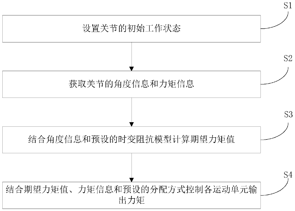
[0060] Such as figure 2 As shown, this embodiment provides a bionic joint control method based on multi-motor drive, including the following steps:

[0061] S1. Set the initial working state of the joint;

[0062] S2. Obtain angle information and moment information of the joint;

[0063] S3. Combining the angle information and the preset time-varying impedance model to calculate the expected torque value;

[0064] S4. Control the output torque of each motion unit in combination with the expected torque value, torque information and preset distribution mode.

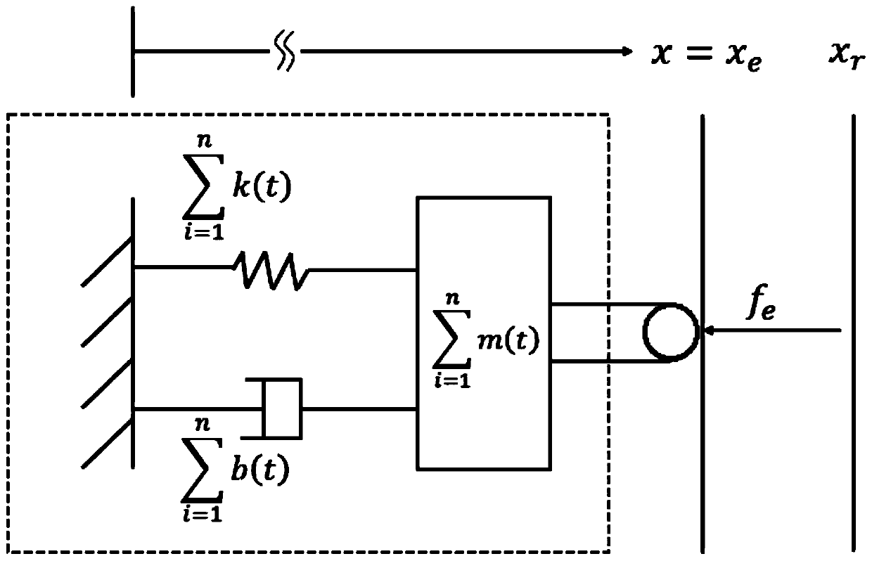
[0065] First set the initial working state of the joint, the joint starts to work in the initial state, collect the angle information at the joint in real time through the encoder or gyroscope and other equipment, collect the torque information at the joint through the torque sensor, and adjust the stiffness of the joint according to the angle information, And calculate the expected torque value according to the chang...


PUM


Abstract

The invention discloses a bionic joint control system and method based on multi-motor drive. The method comprises the following steps of acquiring angle information and torque information of a joint,calculating a desired torque value by combining the angle information and a preset time-varying impedance model, and controlling each motion unit to output torque by combining an expected torque value, the torque information and a preset distribution mode. According to the control system and the control method, a plurality of motors are adopted to jointly drive the joint, the rigidity of the jointis controlled in real time, so that the plurality of motors can effectively cooperate like multiple pieces of muscles of a living being, the flexibility and the variable rigidity performance of the bionic joint are improved, the problems of poor variable rigidity performance, poor control flexibility and the like are solved, and the bionic joint can be widely applied to the technical field of robot joints.

Description

technical field [0001] The invention relates to the technical field of robot joints, in particular to a multi-motor-driven bionic joint control system and method. Background technique [0002] The research and development of bionic robots is a hot spot at home and abroad, and it is also the trend of future research. Joints are the core components of robots. However, the external environment encountered by the robot when performing tasks is uncertain, and it is necessary for the robot to have certain dynamic interaction capabilities when performing tasks. It is difficult for traditional robots to dynamically adjust the joint stiffness according to the external environment and its own load changes to slow down the impact of the external environment. Definitely a safety hazard. Based on this, soft robots and their control methods have been developed. Flexibility control is mainly divided into active flexibility and passive flexibility. Active flexibility control makes the mec...

Claims


Application Information

Patent Timeline
Patent Type & Authority Applications(China)
IPC IPC(8): B25J13/08B25J9/16
CPCB25J9/1633B25J13/085B25J13/087
Inventor 陈丽燕毕盛席宁
Owner 深圳市智能机器人研究院
Why Eureka
Try Eureka