Ceramic slushing forming device

A molding device and pulping technology, which is applied in the field of ceramic processing, can solve problems such as prolonged injection time, defects in the green body, and difficulty in diverting flow, so as to save materials and time, eliminate pinholes in the green body, and realize recycling.

Pending Publication Date: 2019-07-19
福建省德化县豪鹏机械有限公司
View PDF1 Cites 2 Cited by
  • Summary
  • Abstract
  • Description
  • Claims
  • Application Information

AI Technical Summary

Problems solved by technology

The above-mentioned device uses the slurry to be sprayed upwards and is subjected to the impact force of the bottom of the mold to divert the slurry and absorb it inside the mold to form a green body. The thickness is not uniform enough, and there are still some pinholes in the green body
And the above-mentioned device sprays by fixing the nozzle on the lower end of the rotating part. In order to prevent the rotating part from touching the nozzle during the rotation, when the nozzle is facing the grouting port, there is still a certain distance between the nozzle and the grouting port, resulting in When the slurry is sprayed upward, it is easy to splash, resulting in longer injection time, lower efficiency and waste of slurry
Moreover, the above-mentioned device is only suitable for processing ceramic products with a single shape. When the above-mentioned device is used to process ceramic products with a slightly complicated shape, it is difficult for the slurry to flow to every corner and corner of the mold after being sprayed upwards, resulting in the formation of green bodies. With defects, the rate of defective products is high

Method used


Image

  • Ceramic slushing forming device
  • Ceramic slushing forming device
  • Ceramic slushing forming device

Examples


Embodiment Construction

[0020] The present invention will be further described below in conjunction with the accompanying drawings and specific embodiments.

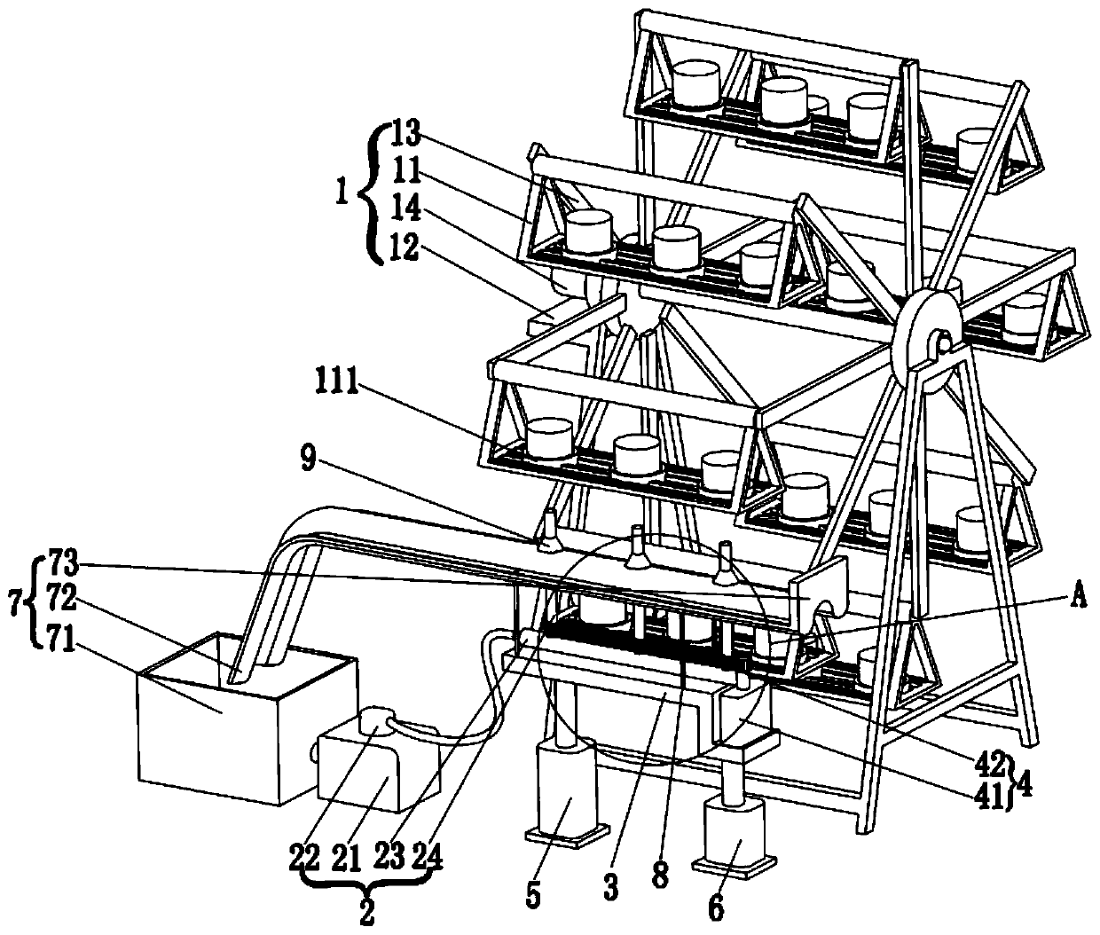
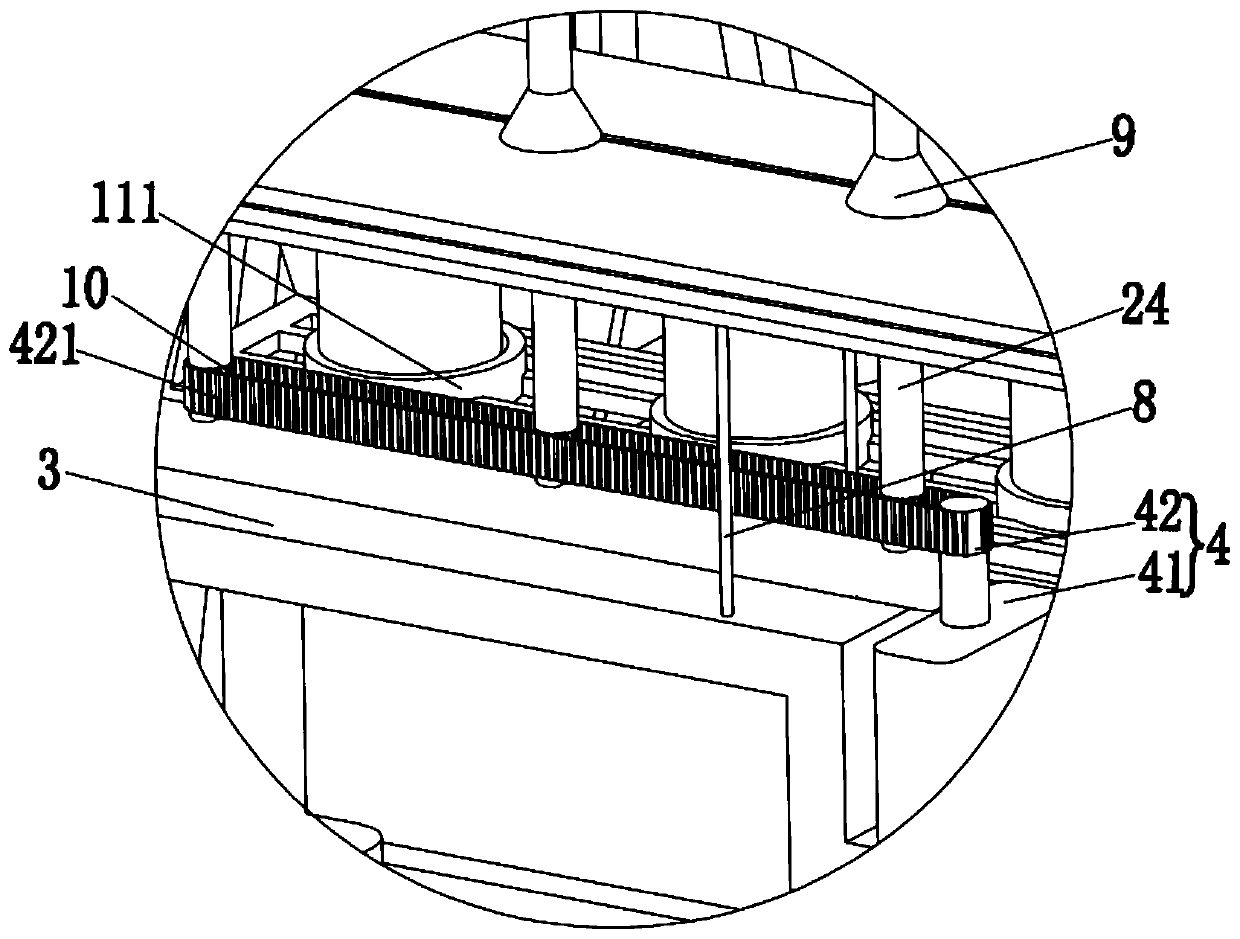
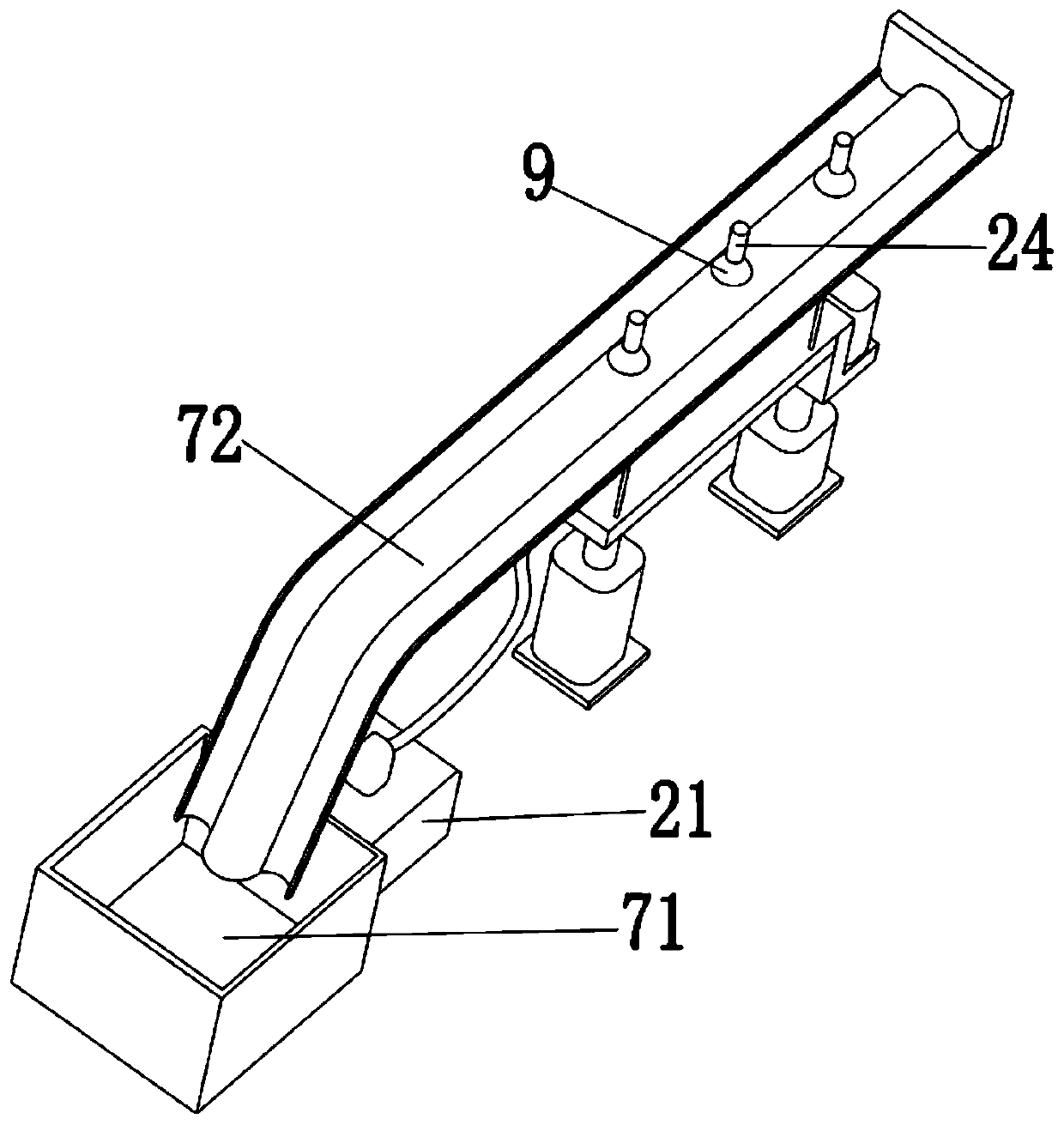
[0021] Such as figure 1 As shown, a ceramic punching device of the present invention includes a rotating device 1 of a water vehicle and a punching device 2, and the rotating device 1 is provided with a plurality of mold racks 11 for placing moulds, and a plurality of said molds The frame 11 is distributed along the circumferential direction of the rotating device 1; the punching device 2 includes a slurry storage tank 21, a punching pump 22, a slurry delivery pipe, a connecting pipe 23 and a plurality of nozzles 24, and the punching pump 22 is set In the slurry storage tank 21, one end of the slurry delivery pipe is connected to the ram pump 22, and the other end is connected to the communication pipe 23, and a plurality of nozzles 24 are arranged above the communication pipe 23, And all are rotatably connected with the communication pipe 23;...


PUM


Abstract

The invention discloses a ceramic slushing forming device. The ceramic slushing forming device comprises a rotating device with a water wheel type and a slushing device, wherein a plurality of mold frames for placing molds are arranged on the rotating device, and the mold frames are distributed in the circumferential direction of the rotating device; the slushing device comprises a slurry storagetank, a stamping pump, a slurry conveying pipe, a communicating pipe and a plurality of spray heads, wherein one end of the slurry conveying pipe is connected with the stamping pump, the other end ofthe slurry conveying pipe is connected with the communicating pipe, and the spray heads are rotatably connected with the communicating pipe; and the low end of the communicating pipe is fixedly connected with a fixed seat, the fixed seat is further provided with a transmission device, a first push-pull device and a second push-pull device are arranged at the lower end of the fixed seat, and the fixed seat moves up and down through the first push-pull device and the second push-pull device. The ceramic slushing forming device is suitable for processing ceramic products with various shapes, a formed blank has uniform thickness, pinholes of the blank can be eliminated, automatic control is adopted, the cost is reduced, and the efficiency is improved.

Description

technical field [0001] The invention relates to the field of ceramic processing, in particular to a ceramic slurry forming device. Background technique [0002] At present, ceramic products with circular cross-sections on the market are usually processed by extrusion molding, while ceramic products with non-circular cross-sections can usually only be processed by grouting molding, which is the conventional method of grouting molding It is to inject the slurry into the mold of the ceramic product, and then discharge the water in the slurry to obtain the green body attached to the mold. However, the operation of this grouting molding process is complicated and requires manual operation, and the production speed is slow and the cost is high. [0003] In order to reduce costs and improve efficiency, there have been equipments that adopt the spray molding process for processing. For example, Chinese patent document CN108274584A (application number 201810256098.5) discloses a cer...

Claims


Application Information

Patent Timeline
Patent Type & Authority Applications(China)
IPC IPC(8): B28B1/26B28B13/02B28B17/00
CPCB28B1/267B28B13/0255B28B13/0275B28B17/00
Inventor 许光权许文豪
Owner 福建省德化县豪鹏机械有限公司
Why Eureka
Try Eureka