Walking wheel assembly

A traveling wheel and assembly technology, applied in conveyor objects, conveyors, mechanical conveyors, etc., can solve the problems of difficult disassembly and maintenance of rotating systems, complex orbital rotating systems, and large space for avoidance, and achieve compact structure. , The effect of flexible rotation and convenient maintenance

Inactive Publication Date: 2019-07-19
DONGFENG LIUZHOU MOTOR
View PDF6 Cites 2 Cited by
  • Summary
  • Abstract
  • Description
  • Claims
  • Application Information

AI Technical Summary

Problems solved by technology

[0003] The problem to be solved by the present invention is to provide a road wheel assembly, which can solve the problem that when the existing road wheel assembly conveying fixture is switched vertically or horizontally, the road wheel assembly, the fixture and the track rotate together, and there is a large space for avoiding the rotation. , and the track rotation system of the walking wheel assembly is complex, expensive, and difficult to disassemble and repair when the rotation system fails

Method used


Image

  • Walking wheel assembly
  • Walking wheel assembly
  • Walking wheel assembly

Examples


Embodiment Construction

[0020] The present invention will be described in further detail below in conjunction with accompanying drawing embodiment:

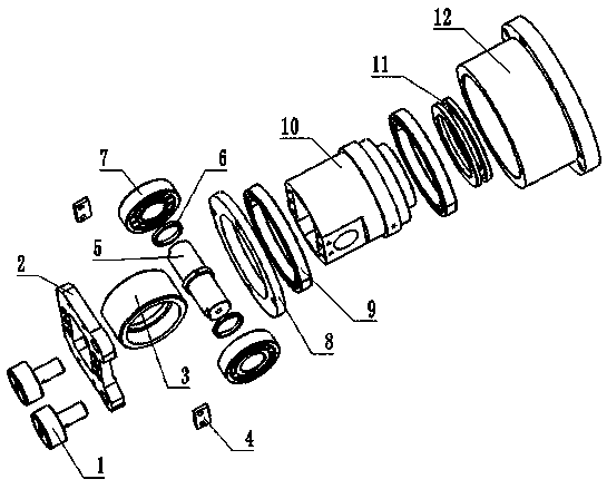
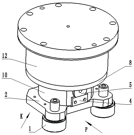
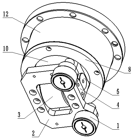
[0021] Such as figure 1 , figure 2 , image 3 A walking wheel assembly shown includes a load-bearing shaft 12 rotatably connected to the upper part of the rotating shaft 10 for placing a fixture. The axis line is basically vertical. The rotating shaft 10 has a cavity with an opening downward, and the traveling wheel 3 is located in the cavity and is mounted on the rotating shaft 10 by the wheel shaft 5. Two first bearings 7 are housed between the wheel shaft 5 and the traveling wheel 3, and the two second bearings An axial limit block fixed on the wheel shaft 5 is installed between the first bearings 7, a spacer 6 is installed on the outer end of the first bearing 7, and a first oil hole for delivering lubricating oil to the first bearing 7 is provided on the wheel shaft 5 ; The first bearing 7 of this embodiment adopts a cylindrical roller bearing...


PUM


Abstract

The invention discloses a walking wheel assembly, and relates to the technical field of automobile production equipment. The walking wheel assembly comprises a bearing shaft which is rotatably connected to the upper part of a rotating shaft and is used for placing a clamp, the lower part of the rotating shaft is provided with a walking wheel, and the axis of the walking wheel is basically perpendicular to the axis of the rotating shaft; and a plurality of guide wheels are arranged at the bottom of the rotating shaft through a mounting plate, and the axle of the guide wheels are basically parallel to the axis of the rotating shaft. According to the walking wheel assembly, compared with the prior art, the walking wheel is located on a track, the guide wheels abut against the side face of thetrack, the track is connected with a switching device for driving the track to rotate, the switching device drives the track to rotate, the rotating shaft is driven to rotate relative to the bearingshaft through the guide wheels, and the walking wheel rotates along with the rotating shaft to realize the longitudinal/transverse switching of the conveying direction, the clamp is arranged on the bearing shaft and does not need to be rotated, the space to be avoided by the walking wheel is small, the rotary structure is simple, and the manufacturing cost is low.

Description

technical field [0001] The invention relates to the technical field of automobile production equipment, in particular to a traveling wheel assembly which can realize longitudinal / transverse switching of conveying direction when conveying fixtures on automobile production line are not rotating. Background technique [0002] At present, the replacement of automobile models is very fast. The production line adopted by the automobile production industry is compatible with the production of various models. The production line needs to switch fixtures according to the production models. The wheel assembly is transported to the storage position, and the production fixture is transported to the working position through the traveling wheel assembly to realize the switching of different vehicle models. It is necessary to change the conveying direction when the traveling wheel assembly transports the fixture to the intersection of the longitudinal and transverse tracks. Since the trave...

Claims


Application Information

Patent Timeline
Patent Type & Authority Applications(China)
IPC IPC(8): B65G35/00B65G47/52
CPCB65G35/00B65G47/52
Inventor 何益富廖勇黄佳华文建东赖春辉李昆霖罗武城
Owner DONGFENG LIUZHOU MOTOR
Why Eureka
Try Eureka