Adhesive tape conveyor return belt cleaning arrangement structure and cleaning method
A belt conveyor and layout structure technology, applied in the direction of conveyors, conveyor objects, cleaning devices, etc., can solve the problems of easy scattering of materials, material accumulation on the return journey of belt conveyors, and environmental pollution, so as to improve economic benefits and layout Reasonable and compact, the effect of improving the environment
- Summary
- Abstract
- Description
- Claims
- Application Information
AI Technical Summary
Problems solved by technology
Method used
Image
Examples
Embodiment 1
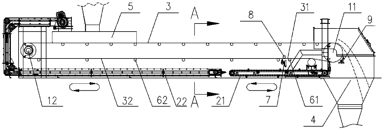
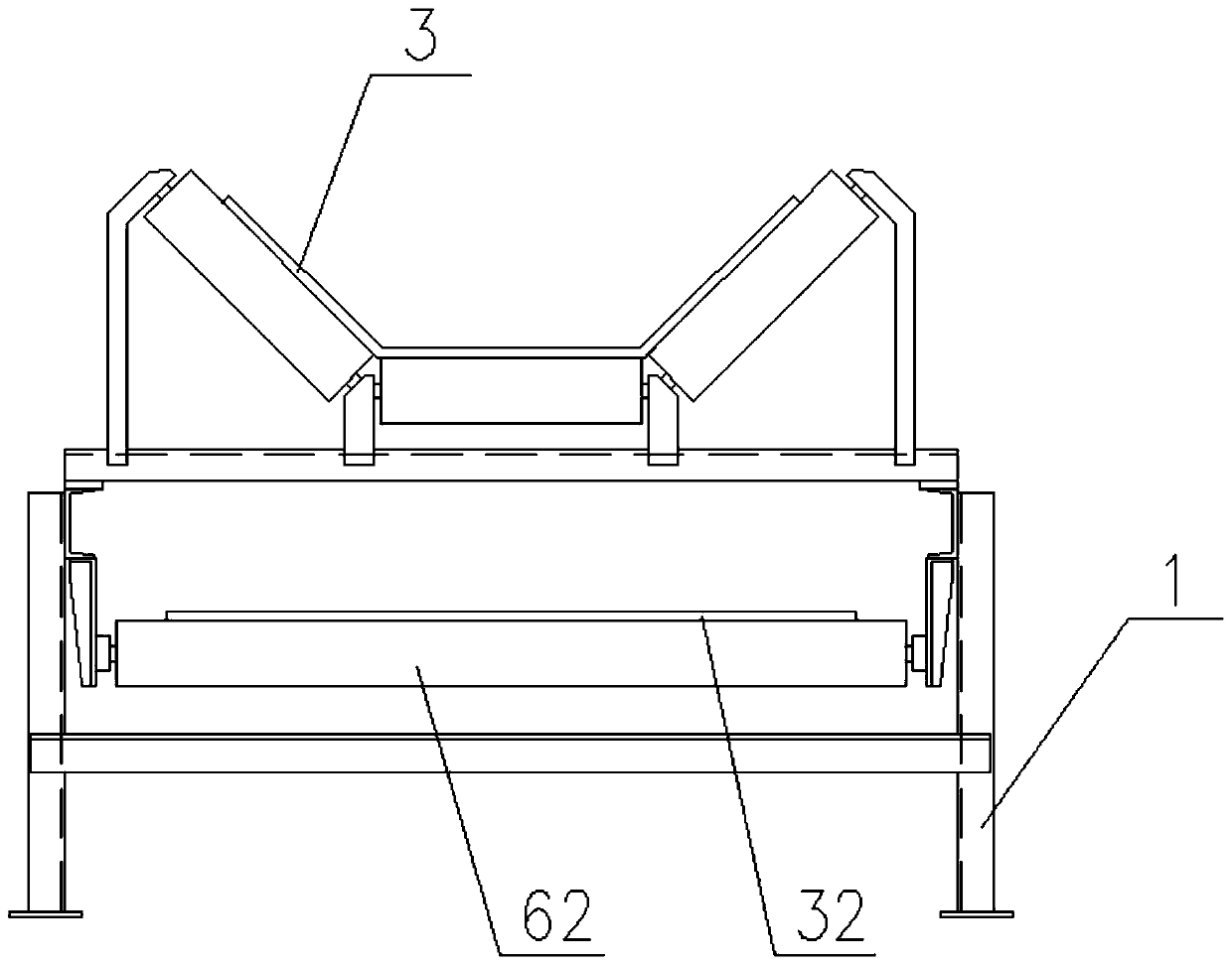
[0053] like figure 1 , figure 2 and Figure 5As shown, in this embodiment, a frame 1 and a conveyor belt 3 are included, and the front and rear ends of the frame 1 are respectively provided with a head drum 11 and a tail drum 12 that drive the conveyor belt 3 to run. The conveyor belt 3 drives the material to be transported from the material guide trough 5 at the rear end of the frame 1 to the discharge port 4 at the front end of the frame 1, and the conveyor belt passes through the head roller 11 to drop the material into the discharge port 4 and then enters the return section area. Conveyor belt 3 comprises the backhaul belt front section 31 and the backhaul belt rear section 32 that are adjacently arranged, and the bottom of the backhaul belt front section 31 is provided with the front section conveying mechanism 21, and the front section conveying mechanism 21 receives the blanking of the return belt front section 31 and sends it into the 1. In the discharge port 4 at t...
Embodiment 2
[0055] like Figure 3 to Figure 5 As shown, in this embodiment, a frame 1 and a conveyor belt 3 are included, and the front and rear ends of the frame 1 are respectively provided with a head drum 11 and a tail drum 12 that drive the conveyor belt 3 to run. The conveyor belt 3 drives the material to be transported from the material guide trough 5 at the rear end of the frame 1 to the discharge port 4 at the front end of the frame 1, and the conveyor belt passes through the head roller 11 to drop the material into the discharge port 4 and then enters the return section area. Conveyor belt 3 comprises return belt front section 31, return belt rear section 32 and the return belt middle section between the return belt front section and the return belt rear section, and the front section conveying mechanism 21 is arranged below the return belt front section 31. The blanking with the front section 31 is sent into the discharge port 4 located at the front end of the frame 1, and the f...
Embodiment 3
[0057] like Image 6 As shown, the difference between this embodiment and Embodiment 2 is that, in this embodiment, the middle section of the bearing device includes a cylindrical roller bearing mechanism and a runner bearing mechanism, and the cylindrical roller bearing mechanism and the runner bearing mechanism are jointly The coordinated layout enables the middle section of the return belt to run stably in a tubular state. Among them, this embodiment includes 7 sets of runner bearing mechanisms and 1 set of cylindrical idler bearing mechanisms. The cylindrical idler bearing mechanism includes an idler supporting frame 634 on which a cylindrical idler 633 is installed. The running wheel carrying mechanism includes a running wheel support frame 632 on which a running wheel 631 is installed. The dirty surface of the middle section of the tubular return belt is located on the inner side, and the lap joint is located at the top of the middle section of the tubular return belt, ...
PUM
 Abstract
Description
Claims
Application Information
 - R&D
- Intellectual Property
- Life Sciences
- Materials
- Tech Scout
- Unparalleled Data Quality
- Higher Quality Content
- 60% Fewer Hallucinations
Browse by: Latest US Patents, China's latest patents, Technical Efficacy Thesaurus, Application Domain, Technology Topic, Popular Technical Reports.
© 2025 PatSnap. All rights reserved.Legal|Privacy policy|Modern Slavery Act Transparency Statement|Sitemap|About US| Contact US: help@patsnap.com


