Method and system for controlling engine fueling

An engine and fuel technology, applied in engine control, engine components, machines/engines, etc., can solve problems such as AFR fluctuation, vapor escape, vapor pressure accumulation limit, etc.

Pending Publication Date: 2019-07-19
FORD GLOBAL TECH LLC
View PDF1 Cites 0 Cited by
  • Summary
  • Abstract
  • Description
  • Claims
  • Application Information

AI Technical Summary

Problems solved by technology

Thereafter, vapor pressure buildup can be limited
As another example, any disturbance in manifold pr...

Method used


Image

  • Method and system for controlling engine fueling
  • Method and system for controlling engine fueling
  • Method and system for controlling engine fueling

Examples


Embodiment Construction

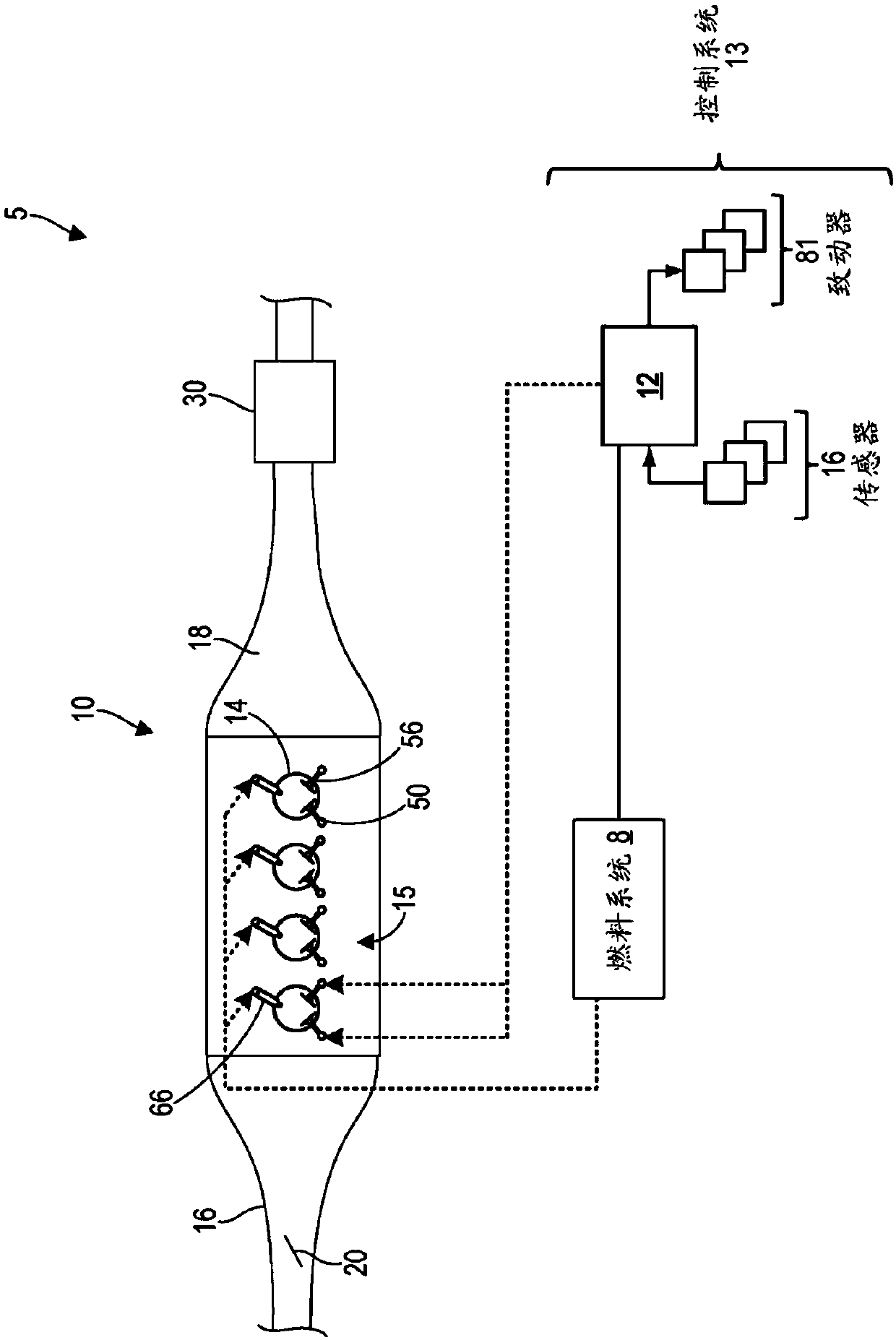
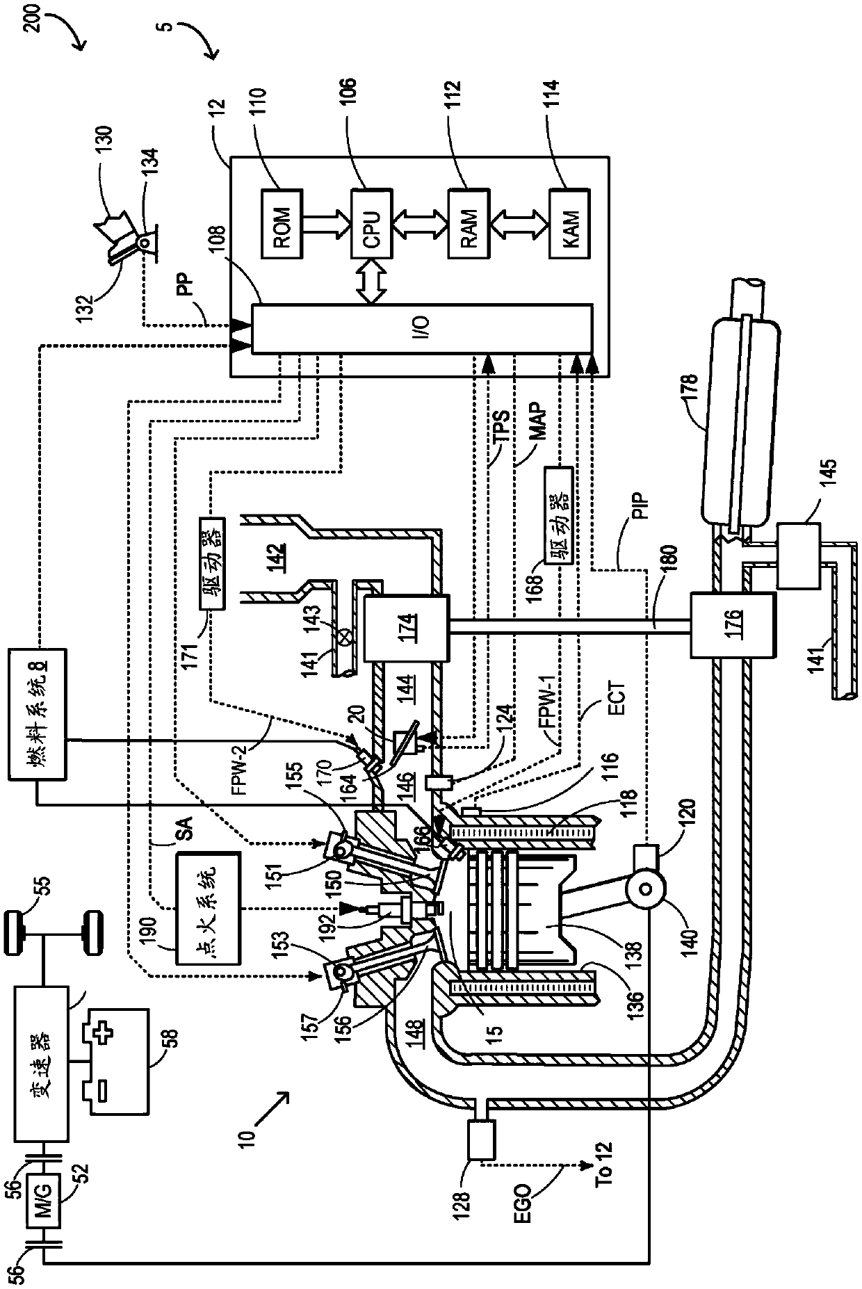
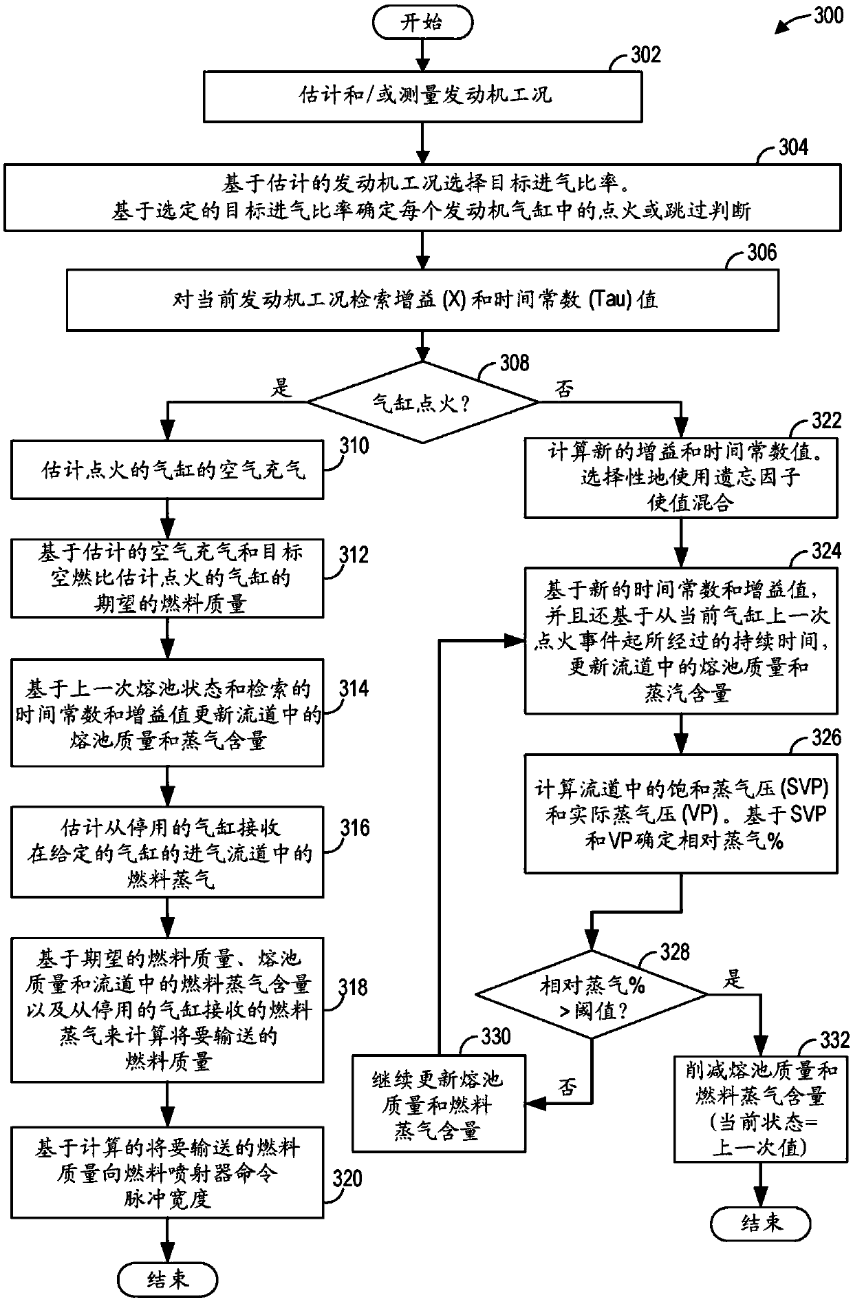
[0017] Provided for use in an engine configured for selective cylinder deactivation in operation such as figure 1 and figure 2 A method and system for adjusting the amount of fuel delivered to cylinders of an engine. The engine controller can execute control programs such as image 3 An exemplary routine to update the fuel pool dynamics for each cylinder based on the cylinder's intake state and based on the given cylinder's firing history. The controller can select gains and time constants to apply to the X-Tau model for transient fuel compensation, such as according to Figure 4 and Figure 5 to compensate for the different fuel pool dynamics of fired versus skipped cylinders. Once the fuel vapor content of the cylinder reaches the saturated vapor pressure limit, the controller can also cut the fuel pool mass, such as Figure 6 shown. exist Figure 7 Exemplary fuel supply adjustments are shown in the prophetic example of , which account for changing fuel pool dynamics...


PUM


Abstract

The disclosure provides a method and system for controlling engine fueling. Methods and systems are provided for tracking a fuel puddle mass in the intake port of a deactivated engine cylinder. The difference in fuel evaporation rate in the deactivated cylinder intake is accounted for by applying distinct time constant and gain values to a transient fuel compensation model. A fuel vapor content isclipped once the intake vapor pressure in the intake port of the deactivated cylinder reaches a saturation pressure limit.

Description

technical field [0001] The present description generally relates to methods and systems for controlling fueling of engine cylinders to compensate for fueling dynamics. Background technique [0002] Controlling an internal combustion engine to maintain a desired air-fuel ratio (AFR) in the combustion chamber reduces emissions. For example, fuel is delivered via electronically controlled fuel injectors that may be coupled inside each engine cylinder or located in the cylinder's intake port. However, not all injected fuel enters the combustion chamber. Instead, some fuel gets stored in the engine's intake manifold, causing a phenomenon commonly known as "wall wetting." For example, in engines configured with port fuel injection, fuel is injected into the intake port aft of the closed intake valve during the non-intake stroke of the cylinder. The injected fuel evaporates quickly due to heat from the valves and mixes with the intake air, then the air-fuel mixture is introduced...

Claims


Application Information

Patent Timeline
IPC IPC(8): F02D17/02F02D41/30F02B77/00
CPCF02B77/00F02D17/02F02D41/3005F02D41/0087F02D41/047F02D2200/1002F02D2200/101F02D41/004F02D41/1401F02D2041/1433F02D2200/0406F02D2200/0604
Inventor 阿迪希亚·普拉瓦伦·雷·兰加埃米·卡尔尼克普拉文·萨西德哈兰戈皮钱德拉·苏尼拉迈克尔·霍华德·谢尔比埃里克·斯托霍克
Owner FORD GLOBAL TECH LLC
Why Eureka
Try Eureka