
Steel-aluminum composite contact rail wear detection system and method

A steel-aluminum composite and detection system technology, applied in the direction of measuring devices, measuring heat, force/torque/power measuring instruments, etc., can solve problems such as fewer detection points, electrical wear, overheating, etc., and achieve fast detection speed and high measurement accuracy , The effect of simple system structure

Pending Publication Date: 2019-07-19
CHINA ACADEMY OF RAILWAY SCI CORP LTD +2
View PDF3 Cites 6 Cited by
  • Summary
  • Abstract
  • Description
  • Claims
  • Application Information

AI Technical Summary

Problems solved by technology

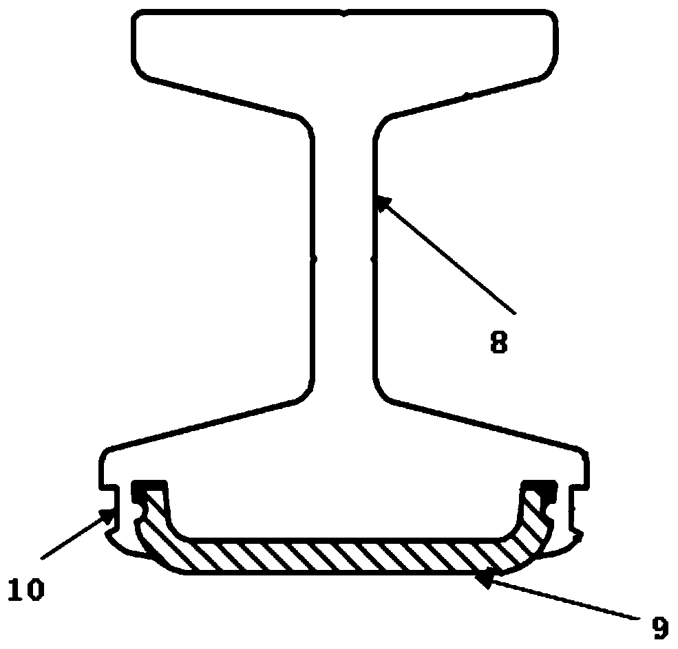
[0004] Check the contact surface of the contact rail with reference to the running rail. The horizontal distance between the center of the contact rail and the inner side of the nearest running rail should be 726.5±5mm, and the vertical distance should be 200±5mm. If the angles of the contact rail and the collector shoe are different, it will The effective contact surface is reduced, local overheating occurs, and severe electrical wear may occur (the electrical wear of the contacts is due to the resistance between the contacts, which will cause the contact layer to melt when the high current is energized, and the In the momentary contact or disconnection, it will even cause air gap breakdown), and then there will be uneven wear of the stainless steel belt of the contact rail
[0005] The general voltage of the contact rail is DC1500V. Manual static measurement of the wear state of the contact surface of the contact rail has low efficiency and heavy workload, and can only be detected within a limited power-off time. There are few detection points and low density, and it is out of train operation. dynamic conditions, which are not conducive to the scientific evaluation management and planned maintenance of the contact rail
If the live work may cause the grounding of the high-voltage end, the power supply will be interrupted, and even the tragedy of electric shock and casualties

Method used


Image

  • Steel-aluminum composite contact rail wear detection system and method
  • Steel-aluminum composite contact rail wear detection system and method
  • Steel-aluminum composite contact rail wear detection system and method

Examples


Embodiment Construction

[0033] In order to make the purpose, technical solutions and advantages of the embodiments of the present invention more clear, the embodiments of the present invention will be further described in detail below in conjunction with the accompanying drawings. Here, the exemplary embodiments and descriptions of the present invention are used to explain the present invention, but not to limit the present invention.

[0034] In order to realize the dynamic detection of the wear of the steel-aluminum composite contact rail when the train is running, an embodiment of the present invention proposes a steel-aluminum composite contact rail wear detection system.

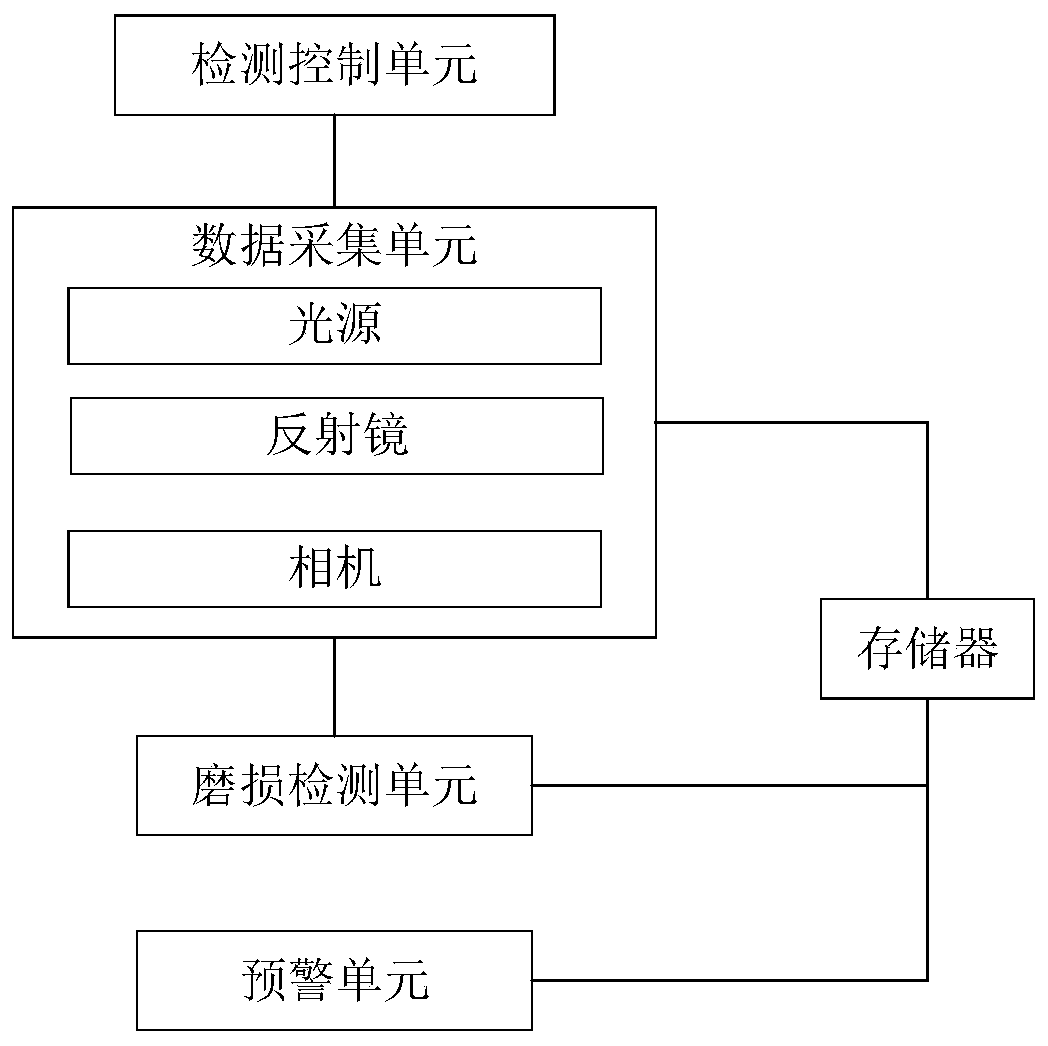
[0035] image 3 It is a schematic diagram of a steel-aluminum composite contact rail wear detection system in an embodiment of the present invention, as image 3 As shown, the system includes:

[0036] A detection control unit, a wear detection unit, a data acquisition unit connected to the detection control unit and the wea...


PUM


Abstract

The invention provides a steel-aluminum composite contact rail wear detection system and method. The system comprises: a detection controller connected with a data collector for transmitting a detection start signal and / or a detection stop signal to the data collector; the data collection installed at the bottom of a train and connected with a wear detector for starting or stopping the collectionof state data of a steel-aluminum composite contact rail according to the received detection start signal and / or the detection stop signal in a running process of the train, and sending the state dataof the steel-aluminum composite contact rail to the wear detector; and the wear detector for receiving the state data of the steel-aluminum composite contact rail and obtaining wear data of the steel-aluminum composite contact rail. By adoption of the steel-aluminum composite contact rail wear detection system and method provided by the invention, the wear of the steel-aluminum composite contactrail can be detected, the structure is simple, the detection speed is high, and the measurement precision is high.

Description

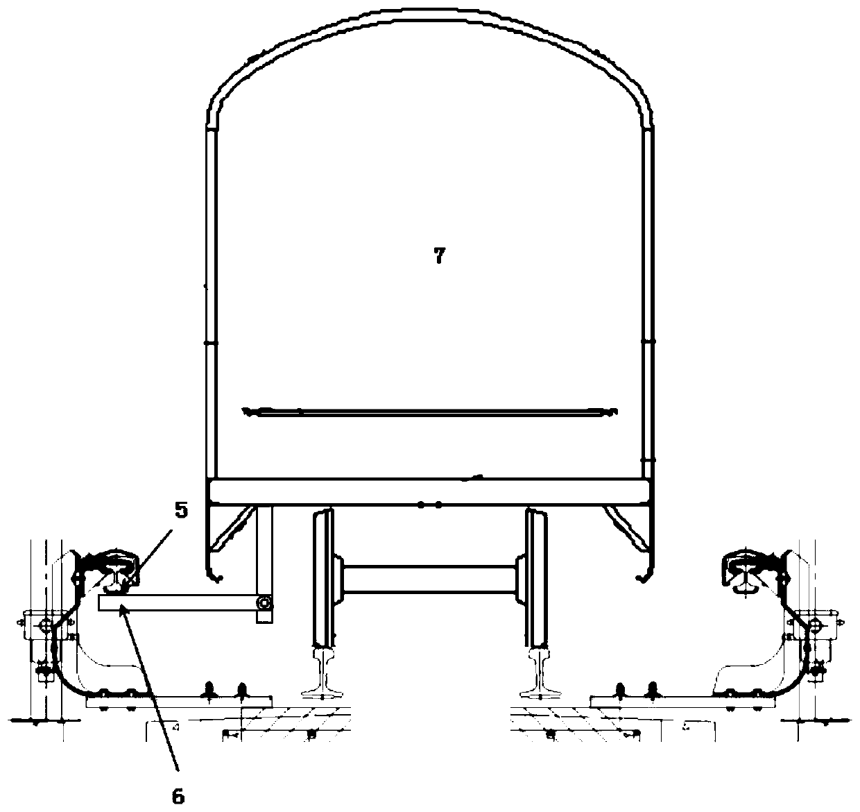
technical field [0001] The invention relates to the field of contact rail wear detection, in particular to a steel-aluminum composite contact rail wear detection system and method. Background technique [0002] The contact rail is a special power supply device that transmits electric energy to electric traction vehicles (electric train units) in subways and urban rail transit systems. The contact rail is arranged along the running rail, and the EMU is contacted by the protruding collector shoe to receive electric energy, providing electric support for all equipment on the rail transit train, such as figure 1 As shown, the positional relationship of the contact rail 5, the collector shoe 6 and the EMU 7 is given. [0003] The steel-aluminum composite contact rail is the main body of the urban rail transit power supply system. It has the advantages of good electrical conductivity, large carrying capacity, light weight, convenient installation, corrosion resistance, and long s...

Claims


Application Information

Patent Timeline
IPC IPC(8): G01B21/00G01B11/00G01B11/24G01L5/00G01K13/00
CPCG01B21/00G01B11/002G01B11/24G01L5/00G01K13/00
Inventor 王琰齐庆海王胜春王昊赵延峰李向东
Owner CHINA ACADEMY OF RAILWAY SCI CORP LTD
Learn More