
An automatic phased array detection device for fillet welds with two-way scanning

A detection device and phased array technology, which is used in measurement devices, instruments, and analysis of solids using sonic/ultrasonic/infrasonic waves, etc. problems, to achieve the effect of improving the detection angle range, improving the detection accuracy, and enhancing the technical effect

Active Publication Date: 2021-09-21
中国石油天然气第一建设有限公司
View PDF11 Cites 0 Cited by
  • Summary
  • Abstract
  • Description
  • Claims
  • Application Information

AI Technical Summary

Problems solved by technology

[0004] 1) Limited by the current domestic standards, the current GB / T32563-2016 (Phased Array Ultrasonic Testing Method) and NB / T47013.3-2015 (Non-destructive Ultrasonic Testing of Pressure Equipment) standards do not involve composite material joints Testing methods for fillet joints;
[0005] 2) Design the ultrasonic testing requirements for the fillet joints of composite material pipes, and the testing cannot be implemented due to the lack of support from testing standards
[0007] 4) Existing ray, conventional A-buried ultrasound, diffraction time-lapse ultrasonic, magnetic particle and penetration testing methods for composite fillet joints all have deficiencies and cannot meet the testing requirements
[0009] Moreover, the existing scanners are only suitable for the detection of straight pipe butt welds, and cannot be used for the detection of curved surface welds between straight pipes of composite materials and vertically welded joints. The fixing method of the detection device and the path of the probe cannot be effectively controlled. Guarantee the completion of inspection work

Method used


Image

  • An automatic phased array detection device for fillet welds with two-way scanning
  • An automatic phased array detection device for fillet welds with two-way scanning
  • An automatic phased array detection device for fillet welds with two-way scanning

Examples


Embodiment 1

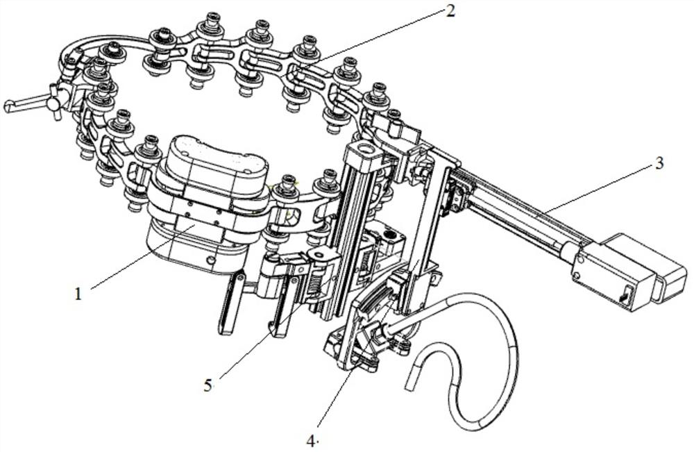
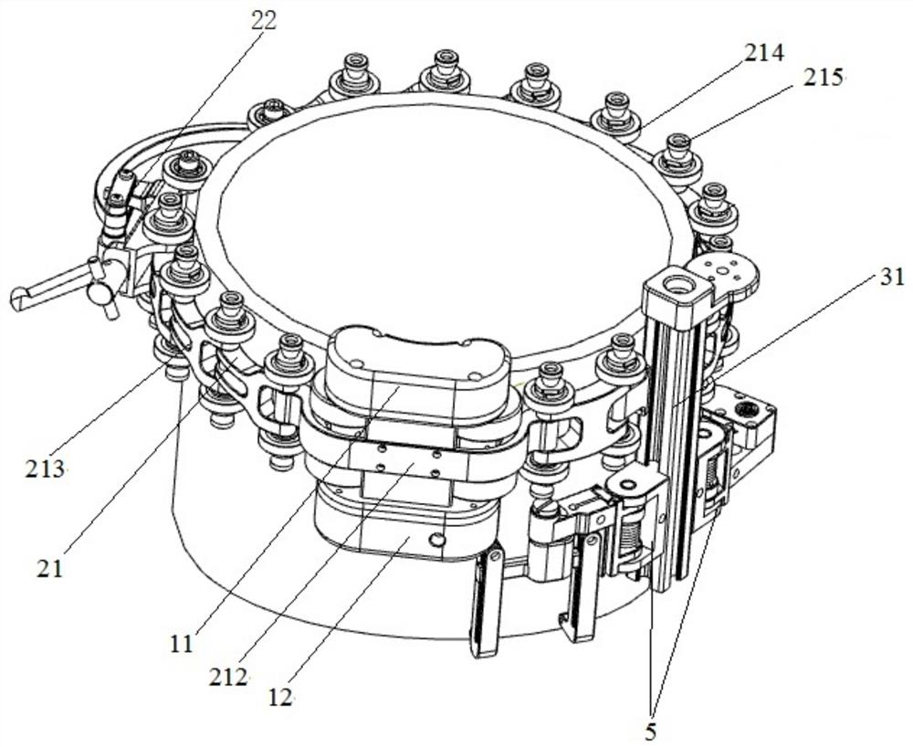
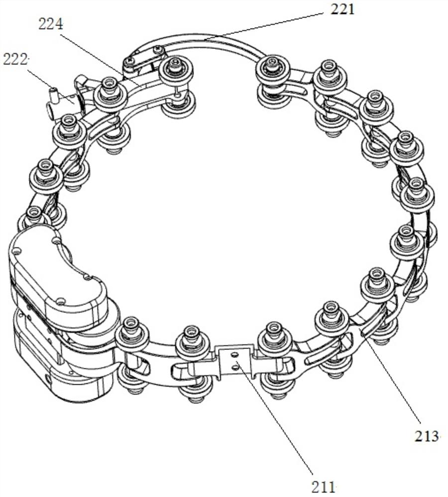
[0046] Such as Figure 1-11 As shown, a phased array detection device for automatic fillet weld seam that can scan bidirectionally in this patent includes a traveling mechanism 1, a locking mechanism 2, an automatic adjustment module 3, a probe frame slide bar assembly 4, and a tube probe arm 5. Control mechanism.

[0047] The traveling mechanism 1 includes two sets of front and rear traveling wheels, a drive motor 11 and a displacement sensor 12; the traveling mechanism 1 is connected to the locking mechanism 2 and arranged on the outer edge of the connecting pipe, and the driving motor 11 and the displacement sensor 12 are respectively arranged on both sides of the traveling mechanism 1; The driving motor 11 drives the traveling wheel to drive the entire scanning device to move clockwise or counterclockwise along the outer diameter of the connecting pipe; the displacement sensor 12 collects the moving distance of the traveling wheel on the outer edge of the connecting pipe a...


PUM


Abstract

The invention introduces a phased array detection device for automatic takeover fillet welds capable of bidirectional scanning, including a traveling mechanism, a locking mechanism, an automatic adjustment module, a probe frame slide bar assembly, a takeover probe arm and a control mechanism; the traveling mechanism It is connected with the locking mechanism and arranged on the outer edge of the connecting pipe; the pull hook and the lock seat plate of the locking component are respectively connected with the two end links of the chain link component to form a complete chain link of the entire locking mechanism; the automatic adjustment module It is fixedly connected with the locking mechanism; the slider mounting plate is fixedly connected with the automatic adjustment module and the probe frame slide bar assembly; the connecting probe arm is arranged on one side of the lower end of the profile rod of the automatic adjustment module. In the technical solution of the present invention, since the wedge and the nozzle wedge of the probe slide bar assembly are provided, the angle range of weld detection is improved, and the detection accuracy is improved; The welding seam is scanned, which enhances the technical effect of the scan.

Description

technical field [0001] The invention relates to the technical field of detection of pipe joint welds, in particular to an automatic phased array detection device for joint fillet welds capable of bidirectional scanning. Background technique [0002] As a green detection method, ultrasonic phased array detection adopts a multi-chip organically arranged probe, uses computer technology to control the sound field deflection, focusing and receiving sound waves of the probe, and uses digital scanning imaging technology to scan at the same time, and the detection results are output as three-dimensional images and storage, providing rich information for defect location, quantification, and characterization; detection data can be analyzed in real time or remotely, with high detection sensitivity, high efficiency, low labor intensity, low detection cost, and safety and environmental protection. [0003] For non-destructive testing of fillet joints of composite pipes, there is currentl...

Claims


Application Information

Patent Timeline
Patent Type & Authority Patents(China)
IPC IPC(8): G01N29/04G01N29/265
CPCG01N29/04G01N29/265G01N2291/0234G01N2291/267
Inventor 龚华王业民胡述超陈厌灾唐建华高建峰华金德周成全张远鹏张登科杨鹏张海武胡贺情叶振林
Owner 中国石油天然气第一建设有限公司
Learn More