Non-turbulent wave infrared electromagnetic wave denitration device

An infrared and electromagnetic wave technology, applied in the field of non-turbulent infrared electromagnetic wave denitrification devices, can solve the problems of increased operating costs and equipment investment, large power consumption, and high operating costs

Pending Publication Date: 2019-07-23
李焕昌
View PDF0 Cites 0 Cited by
  • Summary
  • Abstract
  • Description
  • Claims
  • Application Information

AI Technical Summary

Problems solved by technology

[0002] The denitrification method used today is the ammonia injection method in the SCR catalyst furnace. The catalyst is expensive, the operation cost is high, the emission control efficiency is low, and the ammonia corrosion hazard is caused to the boiler, which affects the combustion...

Method used


Image

  • Non-turbulent wave infrared electromagnetic wave denitration device
  • Non-turbulent wave infrared electromagnetic wave denitration device
  • Non-turbulent wave infrared electromagnetic wave denitration device

Examples


Embodiment Construction

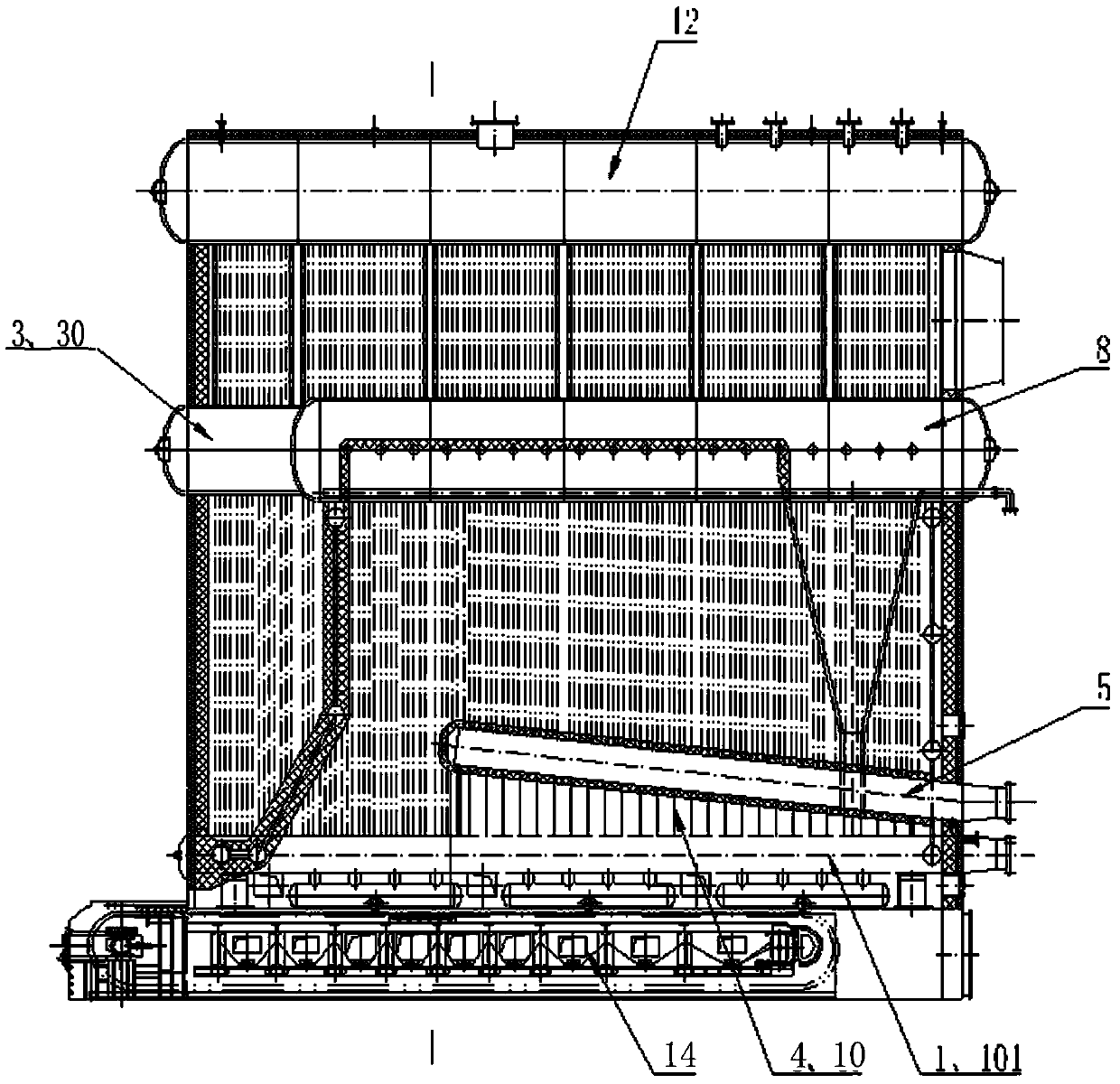
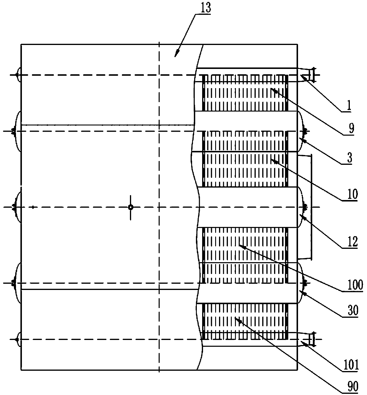
[0025] The invention is a non-turbulent wave infrared electromagnetic wave denitrification device, such as figure 1 As shown, the present invention is composed of three sets of headers in the lower part and four sets of boiler drums in the upper part. The lower header A1, the lower header B101, the left drum 3, and the right drum 30 are connected by a large-arc convection tube to form a beam and focus structure. I-process radiant tube A2, I-process radiant tube B20, II-process outer wall tube A9, II-process outer wall tube B90, and a protective surface 13 built outside the boiler body to form a boiler lower beam and focused non-turbulent infrared electromagnetic wave denitrification device.

[0026] Specifically, the present invention includes the lowermost "thermal oxidation" radiation source structure, the middle I process non-turbulent infrared radiation structure, the central radiation non-turbulent infrared electromagnetic wave denitrification, the II flow arc overlapping...


PUM


Abstract

The invention relates to the field of emission control of infrared electromagnetic wave denitrification oxide Nox-nitrate produced by a boiler, in particular to a non-turbulent wave infrared electromagnetic wave denitration device, which involves a non-turbulent wave infrared electromagnetic wave denitration technology for wave beam and focused non-turbulent wave infrared electromagnetic wave heattransfer by means of infrared electromagnetic waves generated by fuel combustion and a designed arc-shaped tube structure. The non-turbulent wave infrared electromagnetic wave denitration device comprise a lowermost thermal oxidization radiation source structure, a middle flow-I non-turbulent wave infrared radiation structure, a central radiation non-turbulent wave infrared electromagnetic wave denitration device, a flow II arc-shaped overlapped non-turbulent wave infrared electromagnetic wave denitration device, a flow-III arc-shaped tube non-turbulent wave infrared electromagnetic wave denitration device and an outer protection surface. The non-turbulent wave infrared electromagnetic wave denitration device realizes standardized radiation of non-turbulent wave infrared electromagnetic waves through an in-furnace arc-shaped structure, has high denitration efficiency and wide application range, can achieve almost harmless ultra-low concentration, avoids the running cost of emission control, avoids the investment of denitration equipment and lowers the building investment.

Description

technical field [0001] The invention relates to the field of infrared electromagnetic wave denitrification oxide Nox—nitrate emission control field composed of a boiler, in particular to a non-turbulent wave infrared electromagnetic wave denitrification device, which is an infrared electromagnetic wave generated by fuel combustion, and is designed with an arc-shaped tube structure , non-turbulent infrared electromagnetic wave denitrification technology obtained by forming beams and focusing non-turbulent infrared electromagnetic wave heat transfer. Background technique [0002] The denitrification method used today is the ammonia injection method in the SCR catalyst furnace. The catalyst is expensive, the operation cost is high, the emission control efficiency is low, and the ammonia corrosion hazard is caused to the boiler, which affects the combustion condition of the boiler and increases the operating cost and equipment investment and construction investment. SNCR flue ga...

Claims


Application Information

Patent Timeline
IPC IPC(8): B01D53/56B01D53/74
CPCB01D53/56B01D53/74
Inventor 李焕昌杨君王静
Owner 李焕昌
Why Eureka
Try Eureka