Body height control method for pipe rack inspection robot

A technology for inspection robots and pipe galleries, applied to manipulators, program-controlled manipulators, manufacturing tools, etc., to achieve the effect of shortening inspection time

Active Publication Date: 2019-07-23
郑州心忠圆科技有限公司
View PDF4 Cites 1 Cited by
  • Summary
  • Abstract
  • Description
  • Claims
  • Application Information

AI Technical Summary

Problems solved by technology

[0004] The purpose of the present invention is to provide a method for controlling the height of a pipe gallery inspection robot, which solves the problem that since the pipe gallery h

Method used


Image

  • Body height control method for pipe rack inspection robot
  • Body height control method for pipe rack inspection robot
  • Body height control method for pipe rack inspection robot

Examples


Embodiment 1

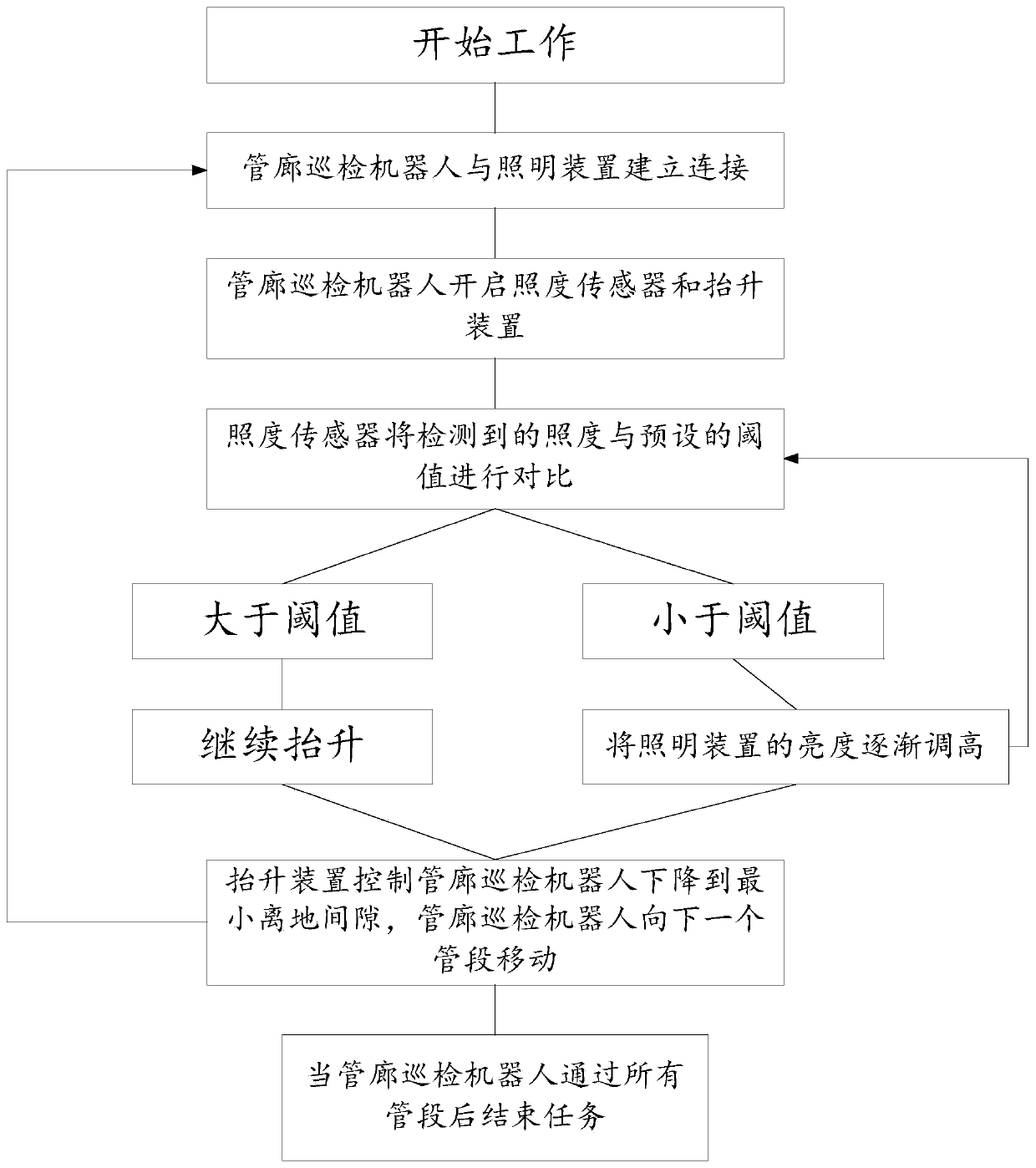
[0029] A method for controlling the height of a pipe gallery inspection robot, comprising a pipe gallery inspection robot with an illuminance sensor, the pipe gallery inspection robot is also provided with a lifting device, and the lifting device is used to adjust the height of the pipe gallery inspection robot Ground clearance, the inspection robot of the pipe gallery and the lighting device in the pipe gallery are equipped with wireless communication devices, and the lighting device is matched with the wireless communication device one by one, and the following steps are also included:

[0030] S1. The pipe gallery inspection robot enters the pipe gallery and starts working;

[0031] S2. The pipe gallery inspection robot stops moving after entering the pipe section where the first lighting device is located, and the wireless communication device of the pipe gallery inspection robot establishes a connection with the wireless communication device of the first lighting device; ...

Embodiment 2

[0039] The difference between this embodiment and Embodiment 1 is that the wireless communication device uses NFC technology for communication. NFC is an emerging technology. Devices using NFC technology can exchange data when they are close to each other. It is evolved from the integration of non-contact radio frequency identification RFID and interconnection technology. By integrating sensing on a single chip With the functions of type card reader, inductive card and point-to-point communication, mobile terminals are used to realize applications such as mobile payment, electronic ticketing, access control, mobile identification, and anti-counterfeiting.

[0040] Further, in the step S6, the pipe gallery inspection robot moves to the next pipe section, and disconnects from the wireless communication device of the previous pipe section after entering the next pipe section. After the corridor inspection robot is disconnected, adjust the brightness of the lighting device connect...

Embodiment 3

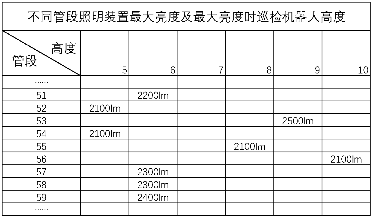
[0045] A kind of data tested in actual work, the illuminance is 0.2lx when the minimum illuminance of all lighting devices is adjusted, and the illuminance threshold detected by the illuminance sensor is 100lx, as shown in Table 1, this device has been used in multiple Different illuminance adjustments are made at heights.

[0046] Table 1: The maximum brightness of different pipe section lighting devices and the height of the inspection robot at the maximum brightness

[0047]


PUM


Abstract

The invention discloses a body height control method for a pipe rack inspection robot. The method is adopted, an inspection machine is ascended to the greatest height from the smallest height after entering a pipe section on which each illuminating device is located; in an ascending process, luminance of a pipe rack is continuously detected; and enough brightness support is guaranteed for image acquisition on each height, i.e., luminance regulation in the pipe rack is performed in a follow-up mode while height of the inspection robot is regulated, so that the problem that height of the pipe rack inspection robot needs to regulate in real time while images are acquired as the pipe rack has certain height is solved, and brightness at all heights is guaranteed to be enough. The body height control method further has the advantages of being energy-saving and environmentally friendly, capable of pre-regulating luminance of the pipe rack, and shortening inspection time.

Description

technical field [0001] The invention relates to the field of control of a pipe gallery inspection robot, in particular to a method for controlling the height of a pipe gallery inspection robot. Background technique [0002] Comprehensive pipe gallery is the comprehensive corridor of underground urban pipelines, that is, to build a tunnel space underground in the city, integrating various engineering pipelines such as power, communication, gas, heating, water supply and drainage, etc., with special inspection ports and hoisting ports and monitoring system, implementing unified planning, unified design, unified construction and management, is an important infrastructure and "lifeline" to ensure the operation of the city Maintenance and repair of municipal facilities such as water supply and drainage. In addition, the system also has a certain effect of earthquake prevention and disaster reduction. For example, during the Great Hanshin Earthquake in Japan in 1995, a large num...

Claims


Application Information

Patent Timeline
IPC IPC(8): B25J11/00B25J19/00B25J9/00
CPCB25J9/00B25J11/00B25J19/00
Inventor 方甲旺
Owner 郑州心忠圆科技有限公司
Why Eureka
Try Eureka