Excimer lamp

An excimer lamp and a part of the technology, applied in the field of excimer lamps, can solve the problems of changes in processing capacity of excimer lamps and reduction of illuminance maintenance rate, and achieve the effect of maintaining illuminance and suppressing the degree of illuminance decline

Active Publication Date: 2013-08-14
USHIO DENKI KK
View PDF3 Cites 0 Cited by
  • Summary
  • Abstract
  • Description
  • Claims
  • Application Information

AI Technical Summary

Problems solved by technology

[0011] However, when an excimer lamp equipped with an ultraviolet reflection layer made of fine particles containing silica particles is turned on for a long time, the illuminance maintenance rate gradually decreases with time.
Therefore, for example, when performing surface treatment such as cleaning treatment, when it is desired to perform treatment with a constant illuminance, there is a problem that the treatment capacity of the excimer lamp changes with the lighting time.

Method used


Image

  • Excimer lamp
  • Excimer lamp
  • Excimer lamp

Examples


Embodiment Construction

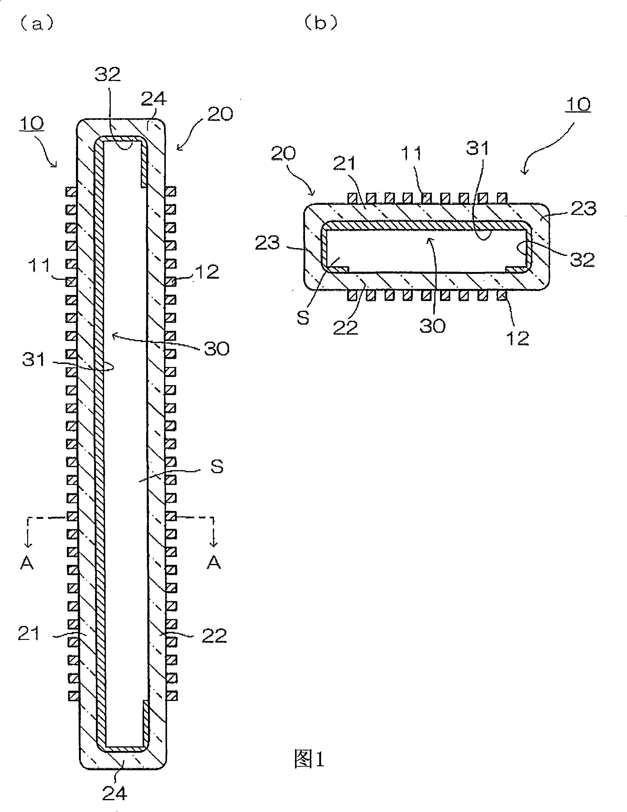
[0032] figure 1 It is an explanatory cross-sectional view showing a schematic configuration of an example of the excimer lamp 10 of the present invention. figure 1 (a) is a sectional view showing a section along the longitudinal direction of the discharge vessel 20, figure 1 (b) means figure 1 (a) Cross-sectional view of A-A' line.

[0033] The excimer lamp 10 includes a hollow long discharge vessel 20 having a rectangular cross-section whose both ends are hermetically sealed and a discharge space S is formed inside. This discharge vessel 20 comprises: an upper wall plate 21 and a lower wall plate 22 relative to the upper wall plate 21; a pair of side wall plates 23 connected to the upper wall plate 21 and the lower wall plate 22; and will be composed of these upper wall plates 21, A pair of end wall plates 24 that are sealed at both ends of the square cylindrical body formed by the lower wall plate 22 and the pair of side wall plates 23 . The discharge vessel 20 is fo...


PUM


Abstract

The invention provides an excimer lamp having an ultraviolet reflection layer, which can inhibit the degree of illumination decrease even after long-term lighting to efficiently emit vacuum ultraviolet light. An excimer lamp (10) with an ultraviolet reflection layer (30) formed on a part of the inner surface of a discharge container (20) is characterized in that the ultraviolet reflection layer (30) comprises: an accumulation body (A31) formed on at least a part of an electrode (11) at one side; and an accumulation body (B32) formed on at least a part outside the area corresponding to the electrode (11, 12), wherein the accumulation body (A31) comprises silicon dioxide particles containing OH groups and micro-particles having melting points higher than that of silicon dioxide, the accumulation body (B32) comprises micro-particles containing silicon dioxide particles having OH groups, and the concentration of OH groups in the silicon dioxide particles forming the ultraviolet reflectionlayer (30) is more than 10 wt ppm.

Description

technical field [0001] The present invention relates to an excimer lamp for performing surface treatment such as cleaning treatment, ashing treatment, and film-forming treatment on an object to be treated by irradiating ultraviolet rays. Background technique [0002] In recent years, the following technology has been developed and put into practical use: irradiating ultraviolet light with a wavelength below 200nm, that is, vacuum ultraviolet light, on glass substrates of liquid crystal display devices, semiconductor wafers, etc. For example, this technology includes cleaning treatment technology for removing organic pollutants adhering to the surface of the object to be processed or oxide film formation treatment technology for forming an oxide film on the surface of the object to be processed. [0003] As a device for irradiating vacuum ultraviolet light, for example, a device equipped with an excimer lamp is used: a discharge gas is sealed in a discharge vessel made of a d...

Claims


Application Information

Patent Timeline
Patent Type & Authority Patents(China)
IPC IPC(8): H01J65/00H01J61/35F21V7/22
CPCH01J5/50H01J9/247H01J61/35H01J65/046H05B41/2806
Inventor 松泽聪司森本幸裕
Owner USHIO DENKI KK
Why Eureka
Try Eureka