Light transmissive material and lamp, and gas treating device and gas treating method

A technology of gas treatment and light transmission, which is applied in the direction of gas treatment, separation methods, gas discharge lamps, etc., can solve the problems of ultraviolet illuminance reduction, illuminance reduction, etc., and achieve the effect of suppressing the reduction of illuminance and easy removal

Pending Publication Date: 2020-11-10
USHIO DENKI KK
View PDF18 Cites 0 Cited by
  • Summary
  • Abstract
  • Description
  • Claims
  • Application Information

AI Technical Summary

Problems solved by technology

[0007] However, since the gas to be treated is in contact with the outer surface of the ultraviolet-transmitting window member, pollutants and the like adhere to the outer surface, and as a result, there is a problem that the illuminance of ultraviolet rays irradiated to the gas to be treated and the photocatalyst is lowered.
[0008] In addition, not only ultraviolet lamps used in gas treatment equipment, but lamps used in environments where dust and pollutants are likely to adhere have the problem that the illuminance of light decreases due to the adhesion of pollutants to the outer surface of the arc tube.

Method used


Image

  • Light transmissive material and lamp, and gas treating device and gas treating method
  • Light transmissive material and lamp, and gas treating device and gas treating method
  • Light transmissive material and lamp, and gas treating device and gas treating method

Examples


Embodiment 1

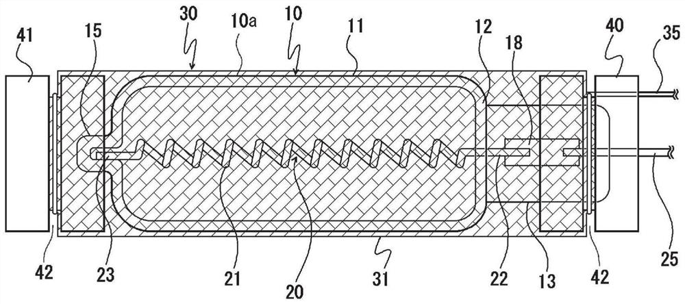
[0115] according to figure 1 With the structure, excimer discharge lamps with the following specifications were manufactured.

[0116] Light-emitting tube (10):

[0117] Material of glass substrate = silica glass

[0118] The material of the surface layer = nano-silica particles with an average particle size of 10nm

[0119] The outer diameter of the light emitting part (11) = 16mm

[0120] The inner diameter of the light emitting part (11) = 14mm

[0121] The length of the light emitting part (11) = 130mm

[0122] Inner electrode (20):

[0123] Material = Tungsten

[0124] Single wire diameter = 0.3mm

[0125] Outer electrode (30):

[0126] Material = stainless steel (SUS304)

[0127] Single wire diameter = 0.2mm

[0128] Enclosed gas:

[0129] Gas Type: Xenon

[0130] Enclosed pressure: 20kPa

[0131] Rated voltage: 4kV

[0132] In the above, the surface layer in the arc tube is formed as follows.

[0133] Inner diameter is 90mm, length is the cylindrical cont...

Embodiment 2

[0136] An excimer discharge lamp having the same specifications as in Example 1 was produced except that nano-silica particles having an average particle diameter of 50 nm were used as nano-silica particles.

[0137] The surface roughness Ra of the outer surface of the arc tube was measured in the same manner as in Example 1 and found to be 12.1 nm.

Embodiment 3

[0139] An excimer discharge lamp having the same specifications as in Example 1 was produced except that the surface layer in the arc tube was formed as follows.

[0140] By immersion method, the dispersion liquid that the average particle diameter is 10nm nano-silica particles is dispersed in the ratio of 30% by mass is applied to the outer surface of the glass substrate that constitutes the arc tube, and left to dry for 72 hours. This forms a skin on the outer surface of the glass substrate.


PUM

PropertyMeasurementUnit
particle sizeaaaaaaaaaa

Abstract

Provided are: a light transmissive material which suppresses contaminants from being attached to the surface thereof, and is capable of easily eliminating the contaminants even when the contaminants are attached; a lamp provided with a light emitting tube comprising the light transmissive material; and a gas treatment device and a gas treating method using said light transmissive material. The light transmissive material of the present invention is obtained by forming a surface layer of nano silica particles on the surface of a glass substrate. The lamp of the present invention is provided with a light emitting tube formed of said light transmissive material, wherein said surface layer is formed on the outer surface of the light emitting tube. The gas treating device of the present invention is provided with: a chamber having a treatment space, in which a gas to be treated flows in the interior thereof; and an ultraviolet ray lamp disposed such that at least a portion of the light emitting tube is exposed to the treatment space, wherein a surface layer of nano silica particles is formed on the outer surface of the light emitting tube in the ultraviolet lamp.

Description

technical field [0001] The present invention relates to a light-transmitting material, a lamp provided with an arc tube made of the light-transmitting material, a gas treatment device and a gas treatment method for treating gas containing harmful substances with ultraviolet rays. Background technique [0002] Conventionally, a method using ultraviolet rays is known as a method for treating gas containing harmful substances. [0003] For example, Patent Document 1 discloses a gas treatment apparatus configured by arranging an ultraviolet lamp emitting vacuum ultraviolet rays having a wavelength of 200 nm or less in a casing through which a gas to be treated flows. In this gas treatment device, active species such as ozone and oxygen radicals are generated by irradiating vacuum ultraviolet rays to oxygen contained in the gas to be treated, and harmful substances contained in the gas to be treated are decomposed by the active species. [0004] In addition, Patent Document 2 di...

Claims


Application Information

Patent Timeline
Patent Type & Authority Applications(China)
IPC IPC(8): H01J61/35B82Y20/00H01J65/00
CPCB82Y20/00H01J61/16H01J65/042H01J61/35A61L9/20A61L9/205A61L2209/12B01D53/007B01D53/8668B01D53/885B01D2255/20707B01D2255/802B01D2257/708B01D2259/804C03C17/25C03C2217/213H01J61/302
Inventor 内藤敬祐
Owner USHIO DENKI KK
Why Eureka
Try Eureka