Pulp block removal equipment for tow used in chemical fiber spinning production

A pulp block and tow technology is applied in the field of pulp block removal equipment for tow used in chemical fiber spinning production, and can solve the problems of low efficiency, difficult treatment, and influence on pulp block removal.

Active Publication Date: 2021-03-30
杭州卓维机械有限公司
View PDF13 Cites 0 Cited by
  • Summary
  • Abstract
  • Description
  • Claims
  • Application Information

AI Technical Summary

Problems solved by technology

[0004] However, in the comparative patent CN207793517U, the slurry sticks to the tow and passes through simple short blades and long blades, and the efficiency is extremely low, and the removed pulp will never be attached to the blade, which is difficult to handle, and it is difficult to handle when it continues to work. Affects pulp removal

Method used


Image

  • Pulp block removal equipment for tow used in chemical fiber spinning production
  • Pulp block removal equipment for tow used in chemical fiber spinning production
  • Pulp block removal equipment for tow used in chemical fiber spinning production

Examples


Embodiment 1

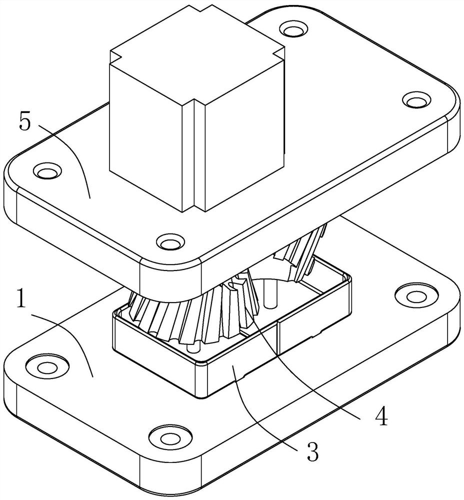
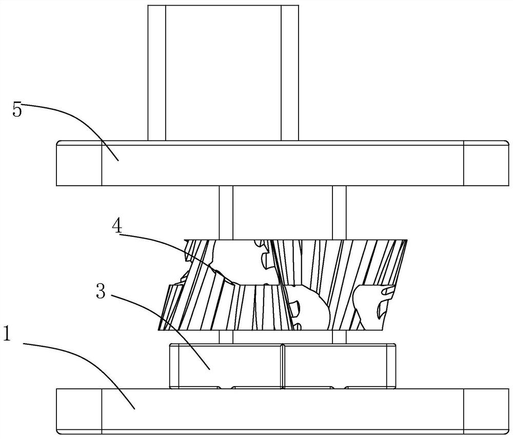
[0037] Such as Figure 1-8 As shown, the present invention provides a technical solution: a slurry block removal device for a filament beam of a chemical fiber spinning, including mounting plate A1, two mounting grooves 2, collecting device 3, slurry block removal device 4, and mounting plate B5. The two mounting grooves 2 are symmetrically opened on the upper surface of the mounting plate A1, and the bottom portion of the collecting device 3 is connected between the mounting groove 2, and the slurry block removal device 4 is disposed between the mounting plate B5 and the collecting device 3, the mounting plate A1 is installed. On the winding machine, and, the removal is performed by the slurry block removal device 4, and the collection of the selection device 3 can be achieved, and the four angles of the mounting plate A1 and the mounting plate B5 can be installed. The bolt slot 6 is used for easy installation operation.

[0038] The collecting device 3 includes two collecting cas...

Embodiment 2

[0041] Such as Figure 1-8 As shown, in the basis of the first example, the present invention provides a technical solution: there is a spacing between the two cone braking heads 403, and its spacing ensures normal movement of the wire beam, and it is not easy to break the wire beam, which is easy to break The removal of a slurry block is performed.

Embodiment 3

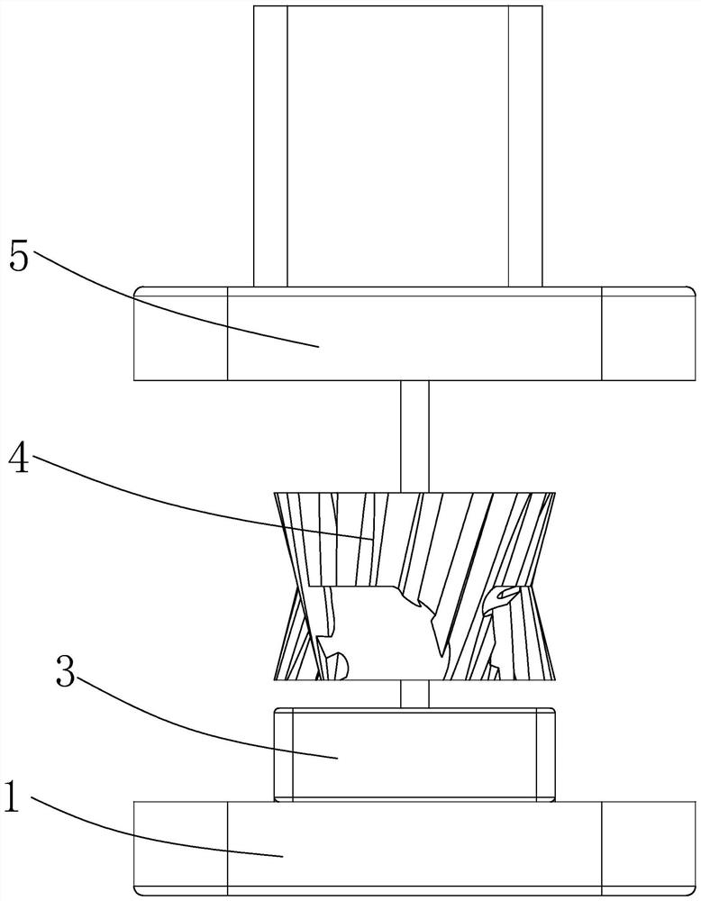
[0043] Such as Figure 1-8As shown in the basis of the first embodiment, the present invention provides a technical solution: the number of recessed portions 404 is six, and three recessed portions 404 are group, each set of three recesses 404. Symmetrical setting with the central axis of the taper tooth grinding head 403.

[0044] The vertical depth of the recessed portion 404 is slightly less than one-half of the height of the cone joining head 403, ensuring that the steering beam located at the center can be taken out to remove the slurry block.


PUM


Abstract

The invention relates to the technical field of chemical fiber spinning production, in particular to slurry block removal equipment of tows for chemical fiber spinning production. The equipment comprises a mounting plate A, two mounting grooves, a collecting device, a slurry block removal device and a mounting plate B; the two mounting grooves are symmetrically formed in the upper surface of the mounting plate A, the bottom of the collecting device is connected with the mounting grooves, and the slurry block removal device is arranged between the mounting plate B and the collecting device. Thecollecting device comprises two collecting boxes, mounting blocks adaptive to the mounting grooves are fixedly connected to the bottoms of the collecting boxes and inserted in the surfaces of the mounting grooves, and one sides and the upper portions of the two collecting boxes are provided with openings. According to the equipment, through the arrangement of conical tooth grinding heads and sunken parts, during rotation, the tows between the two conical tooth grinding heads can be moved, and slurry blocks attached to the surfaces of the tows can be removed at the same time; meanwhile, when the two conical tooth grinding heads are driven, vibration occurs during pressing, and the slurry blocks are convenient to remove.

Description

Technical field [0001] The present invention relates to the technical field of chemical fiber spinning production, and it is specifically referred to as a slurry block removal of a wire beam for chemical fiber spinning. Background technique [0002] In the production of chemical fiber spinning, such as the drying of the wire, the slurry bump ejected through the spinneret is often carried out by the various process reasons, which will affect normal production. [0003] Current treatment methods, such as: Chinese Patent CN207793517U, a new type of slurry block removal device, including mounting plates, fixed blocks, adjustment spacers, top screws, short blades, long blades, and long round holes on mounting plates, fixed There is a rectangular via hole in the middle of the block, and the two sides are flat and a threaded hole, the mounting plate and the fixed block group are welded into one; short blade, several adjustment spacers, long blade through the top of the fixed blocks The ...

Claims


Application Information

Patent Timeline
Patent Type & Authority Patents(China)
IPC IPC(8): D01D10/00
CPCD01D10/00
Inventor 王晓明郦金香周明
Owner 杭州卓维机械有限公司
Why Eureka
Try Eureka