Pump shaft sleeve

A technology of pump shaft sleeves and shaft sleeves, which is applied in the field of pump shaft sleeves and pump shaft sleeves for circumferential positioning at the end of the shaft sleeves. It can solve the problems of reducing the strength of the rotor, increasing the length of the pump shaft, and increasing the size of the shaft diameter. Achieve the effect of shortening the length of the pump shaft and enhancing the strength of the rotor

Pending Publication Date: 2019-07-23
HUNAN MECHANICAL & ELECTRICAL POLYTECHNIC +1
View PDF0 Cites 2 Cited by
  • Summary
  • Abstract
  • Description
  • Claims
  • Application Information

AI Technical Summary

Problems solved by technology

Due to the thicker wall thickness, these two types of bushings are generally cast, but casting of thicker thick-walled parts or parts with uneven thickness is prone to defects, and the scrap rate is very high
In addition, for pumps conveying high-temperature or corrosive media, in order to prevent the impeller and impeller retaining sleeve or the big head part of the shaft sleeve from infiltrating the medium between the shaft sleeve and the pump shaft due to casting defects and leaking from the tail end of the shaft sleeve, it is generally necessary Install an "O" seal ring between the shaft sleeve and the shaft sleeve. In the above two cases, the "O" seal ring cannot be installed at the front end of the shaft sleeve due to the keyway connecting the flat key, so only a short sleeve can be added at the end of the shaft sleeve. To install the "O" type sealing ring, this increases the length of the pump shaft and reduces the strength of the rotor, or increases the cost by increasing the shaft diameter to ensure the strength of the rotor

Method used


Image

  • Pump shaft sleeve
  • Pump shaft sleeve
  • Pump shaft sleeve

Examples


Embodiment Construction

[0014] The present invention will be further described below in conjunction with the accompanying drawings and specific embodiments.

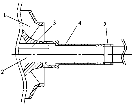
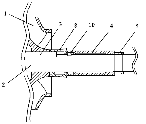
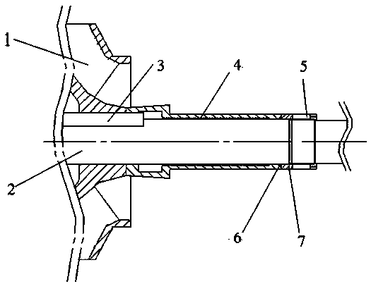
[0015] Pump shaft sleeve, including shaft sleeve 4, shaft sleeve nut 5, "O" type seal ring 6, impeller retainer sleeve 8 and "L" type key 9, after the impeller flat key 3 and impeller 1 are installed on the pump shaft 2, Install the impeller retaining sleeve 8, "O" type seal ring 6, shaft sleeve 4, "L" type key 9 and shaft sleeve nut 5 on the pump shaft in sequence. The tail end of the impeller retaining sleeve 8 is a plane, the front end of the shaft sleeve 4 does not have a keyway, but has a 45° chamfer, and the "O" type seal ring 6 is installed on the outer circle of the pump shaft 2 1. The triangular position between the plane of the tail end of the impeller block sleeve 8 and the 45° chamfer at the front end of the shaft sleeve 4 is used to seal the outward leakage of the medium between the shaft sleeve 4 and the pump shaft 2 . The tail e...


PUM


Abstract

The invention provides a pump shaft sleeve. The pump shaft sleeve comprises an impeller spacer sleeve, an O-shaped sealing ring, a shaft sleeve body, an L-shaped key and a shaft sleeve nut. The tail end of the impeller spacer sleeve is provided with a plane. The front end of the shaft sleeve is not provided with a key groove but is provided with a 45-degree chamfer. The O-shaped sealing ring is mounted in a triangular area formed between the outer circle of a pump shaft, the plane of the tail end of the impeller spacer sleeve and the 45-degree chamfer of the front end of the shaft sleeve body.The tail end of the shaft sleeve body is provided with a notch. The L-shaped key has two sides, one side is mounted in a key groove of the pump shaft, and the other side is mounted in the notch of the tail end of the shaft sleeve body. The shaft sleeve nut is axially located on the pump shaft. The shaft sleeve can be machined from a thick-wall steel tube without casting. According to the pump shaft sleeve locating structure, the O-shaped sealing ring can be mounted at the front end of the shaft sleeve to prevent medium leakage without increasing the length of the pump shaft. Before the shaftsleeve nut is tightened, an impeller, the impeller spacer sleeve, the O-shaped sealing ring, the shaft sleeve body and the L-shaped key all can move on the pump shaft in the axial direction to achievethe axial position regulating function.

Description

technical field [0001] The invention belongs to the technical field of water pumps, and relates to a pump shaft sleeve, in particular to a pump shaft sleeve which is circumferentially positioned at the tail end of the shaft sleeve. Background technique [0002] The pump shaft sleeve is a common wearing part in the pump structure. It is mainly used in conjunction with the seal to prevent the medium from leaking out of the pump. It is designed to protect the pump shaft. The position between the pump shaft sleeve and the main shaft is generally as follows: use a flat key at the front end of the shaft sleeve for circumferential positioning and use a shaft sleeve nut or round nut for axial positioning at the tail end. This positioning method requires that the front end of the shaft sleeve has sufficient wall thickness to install the flat key, and the wall thickness of the shaft sleeve itself is relatively thin. Generally, the impeller retainer sleeve and the shaft sleeve are desi...

Claims


Application Information

Patent Timeline
Patent Type & Authority Applications(China)
IPC IPC(8): F04D29/043
CPCF04D29/043
Inventor 余学军何群林彭兆静聂葵毛泓杨翠明刘小兵夏仲林
Owner HUNAN MECHANICAL & ELECTRICAL POLYTECHNIC
Why Eureka
Try Eureka