
Canal valve for modern agricultural production

A technology for water channels and valves, applied in the direction of sliding valves, valve devices, engine components, etc., can solve the problems of pollution and waste, poor lubricating effect of lubricating oil, etc., and achieve the effect of ensuring purity, good lubricating effect, and improving lubricating effect

Active Publication Date: 2019-07-23
浙江农丰软管股份有限公司
View PDF4 Cites 0 Cited by
  • Summary
  • Abstract
  • Description
  • Claims
  • Application Information

AI Technical Summary

Problems solved by technology

[0005] The purpose of the present invention is to provide a modern agricultural production method with simple operation, good lubricating effect and less waste, aiming at the problem that lubricating oil has poor lubricating effect and is easy to cause pollution and waste during the oiling process of the existing valve. water drain valve

Method used


Image

  • Canal valve for modern agricultural production
  • Canal valve for modern agricultural production
  • Canal valve for modern agricultural production

Examples


Embodiment 1

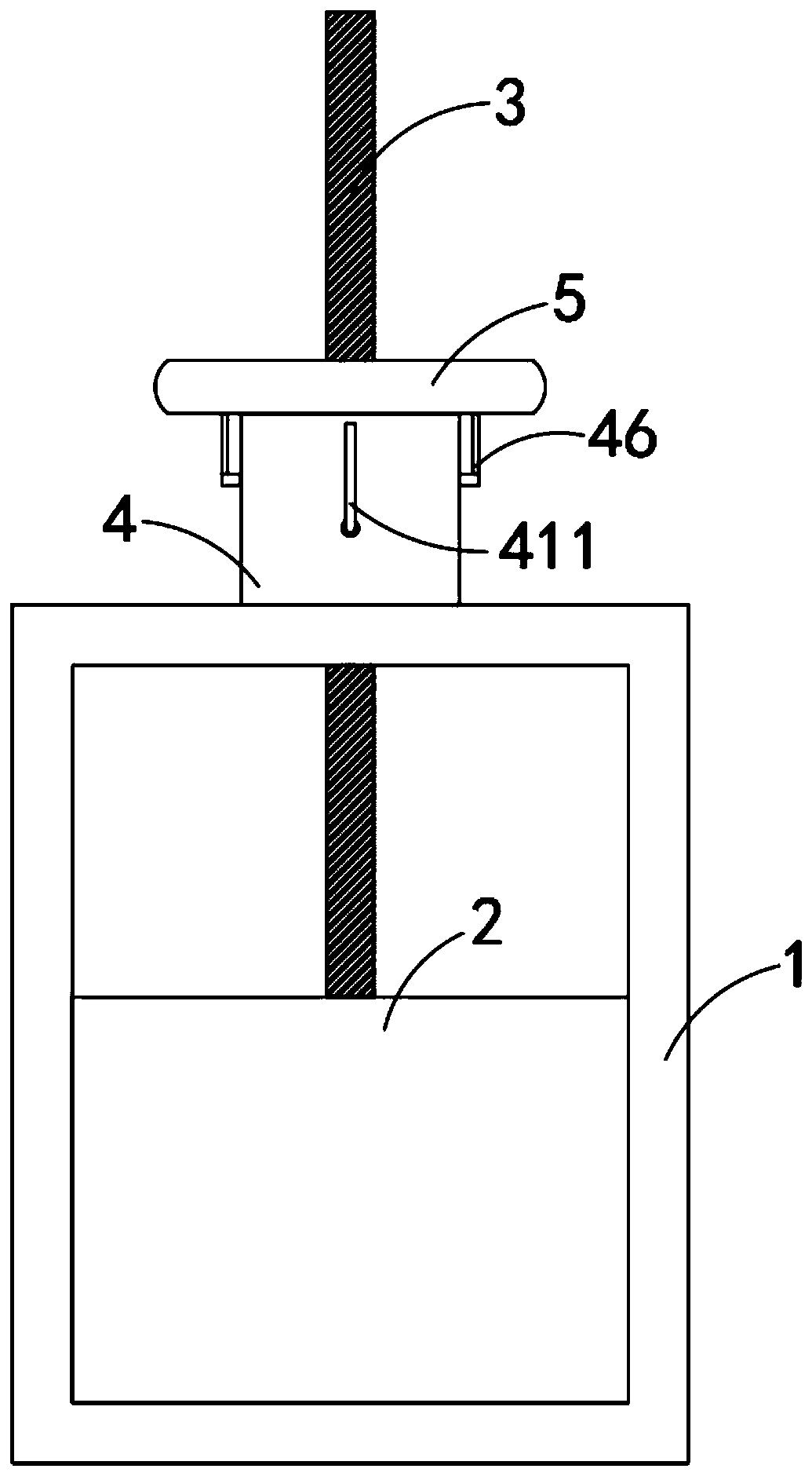
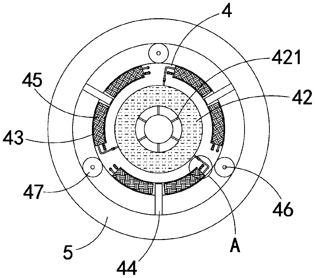
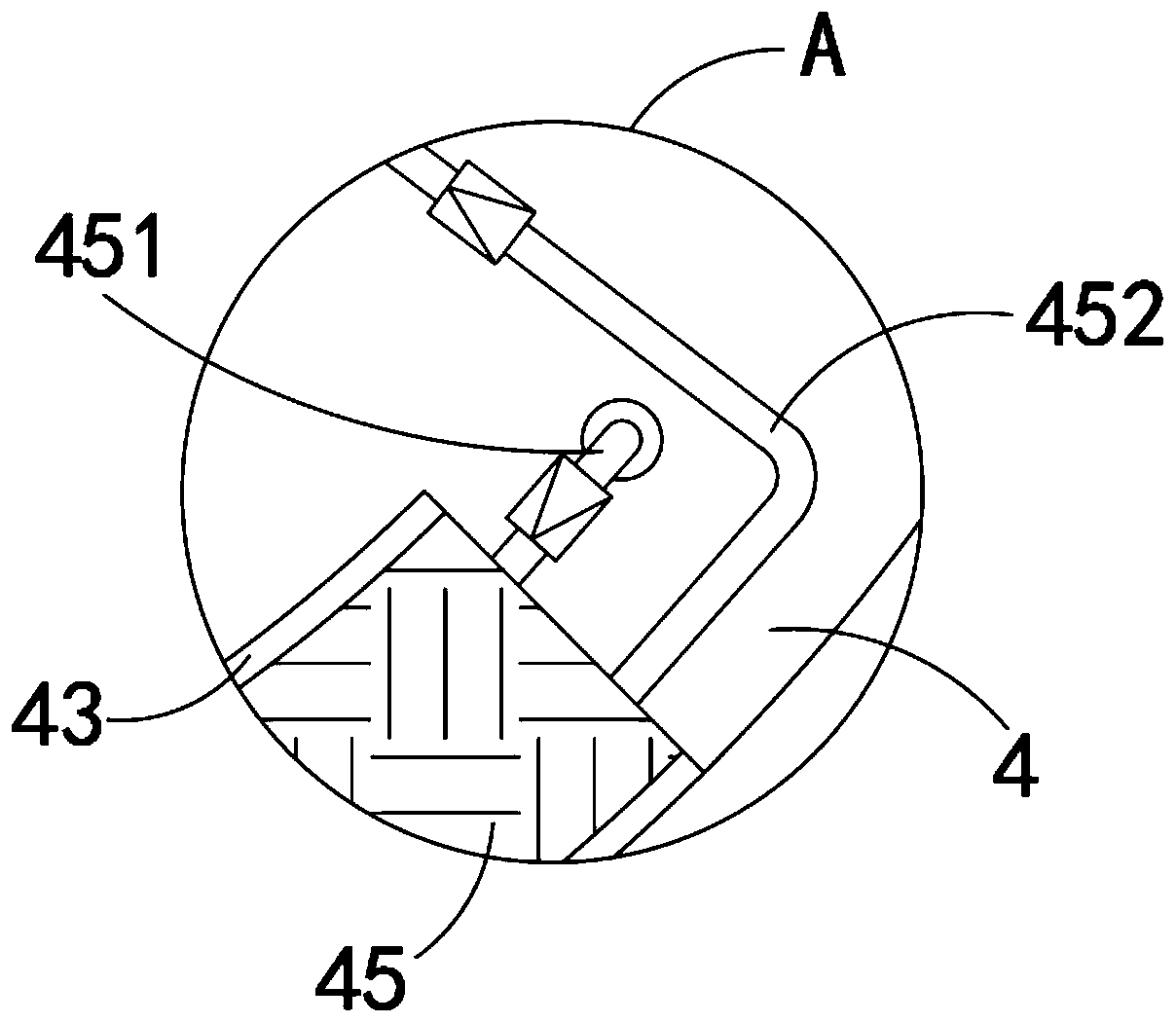
[0028] Such as Figure 1-4 As shown, a modern agricultural production canal valve includes a valve frame 1, a valve plate 2, a threaded rod 3, a rotating sleeve 4 and a rotating ring 5, the lower end of the rotating sleeve 4 is rotatably connected to the upper end of the valve frame 1, and the rotating The sleeve 4 is provided with a thread groove, the threaded rod 3 runs through the rotating sleeve 4 and is threadedly connected with the rotating sleeve 4, and the rotating sleeve 4 is provided with:

[0029] The liquid storage chamber 41, the side wall of the liquid storage chamber 41 is fixedly connected with an oil inlet pipe 411, and the oil inlet pipe 411 communicates with the lower bottom of the oil storage chamber 41;

[0030] Two annular temporary storage chambers 42, two annular temporary storage chambers 42 are respectively arranged on the upper and lower sides of the liquid storage chamber 41, and the side walls of the annular temporary storage chambers 42 are provid...

Embodiment 2

[0036] Such as Figure 5 As shown, the difference between this embodiment and Embodiment 1 is: the input end of the oil inlet pipe 411 is bent to a horizontal state, and the input end of the oil inlet pipe 411 is rotatably connected with an L-shaped joint 412, and the oil inlet pipe 411 is made of transparent material , The pipe wall of the oil inlet pipe 411 is provided with a scale line, which can facilitate the observation of the remaining oil in the oil storage chamber 41 .

[0037] In this embodiment, by setting the L-shaped joint 412, the opening of the L-shaped joint 412 faces downward in the non-oiling state, so as to prevent dust or other sundries from entering the oil storage chamber 42, so as to ensure the purity of the lubricating oil. Improve the lubrication effect.


PUM


Abstract

The invention belongs to the technical field of modern agriculture, in particular to a canal valve for modern agricultural production. The canal valve for the modern agricultural production comprisesa valve frame, a valve plate, a threaded rod, a rotating sleeve and a rotating ring, wherein the lower end of the rotating sleeve is rotationally connected with the upper end of the valve frame, a threaded groove is arranged in the rotating sleeve, and the threaded rod passes through the rotating sleeve and is in threaded with the rotating sleeve; the rotating sleeve is provided with a liquid storage cavity, two annular temporary storage cavities and a plurality of arc-shaped sliding grooves, wherein the side wall of the liquid storage cavity is fixedly connected with an oil inlet pipe; the two annular temporary storage cavities are respectively arranged at the upper and lower sides of the liquid storage cavity, and oil drain holes communicating with the inner side wall of the rotating sleeve are formed in the side wall of the annular temporary storage cavities; the arc-shaped sliding grooves are formed on the outer side wall of the rotating sleeve, and the arc-shaped sliding grooves are uniformly distributed along the circumferential side wall of the rotating sleeve. The canal valve provided by the invention can complete the oil filling of the rotating sleeve automatically duringthe process of rotating the rotating ring, and the canal valve has simple operation not only, but also is less likely to cause pollution and waste of lubricating oil.

Description

technical field [0001] The invention belongs to the technical field of modern agriculture, and in particular relates to a modern agricultural production water channel valve. Background technique [0002] Agricultural modernization refers to transforming traditional agriculture into modern agriculture, establishing agriculture on the basis of modern science, using modern science and technology and modern industry to equip agriculture, using modern economic science to manage agriculture, and creating a high-yield, high-quality, and low-consumption environment. Agricultural production system and an agro-ecosystem that utilizes resources rationally, protects the environment, and has high conversion efficiency. [0003] At present, in the process of using the canal valves used in modern agricultural production, in order to increase the flexibility of the threaded rod and reduce the difficulty of operation, it is generally necessary to apply lubricating oil to the gap between the ...

Claims


Application Information

Patent Timeline
IPC IPC(8): F16K3/36F16K3/02F16K3/30
CPCF16K3/02F16K3/30F16K3/36
Inventor 邵金国
Owner 浙江农丰软管股份有限公司
Learn More