Supercharge Your Innovation With Domain-Expert AI Agents!

Pipeline type gasification device

A gasification device, pipeline technology, applied in pipeline systems, gas/liquid distribution and storage, mechanical equipment, etc., can solve the problems of short reaction stroke, large space occupation, unreacted space utilization, etc., to extend the reaction stroke , convenient for precise control and the effect of reducing the footprint

Active Publication Date: 2019-07-23
中国煤层气集团有限公司
View PDF12 Cites 0 Cited by
  • Summary
  • Abstract
  • Description
  • Claims
  • Application Information

AI Technical Summary

Problems solved by technology

[0004] Traditional reaction devices are mostly tank-shaped or box-shaped, which occupy a large space and have a short reaction process, which does not make full use of the reaction space, and is not convenient for precise control of pressure and temperature
[0005] The coal-to-methane gas reactor in the traditional technology is usually in the shape of a tank. Through high temperature and high pressure, the hydrocarbon components in the coal are pyrolyzed and methane is catalyzed by the inducer. However, due to the contact time between the coal and the inducer in the traditional reaction device Shorter formation with reaction, less efficient methane gas generation

Method used


Image

  • Pipeline type gasification device
  • Pipeline type gasification device
  • Pipeline type gasification device

Examples


Embodiment 1

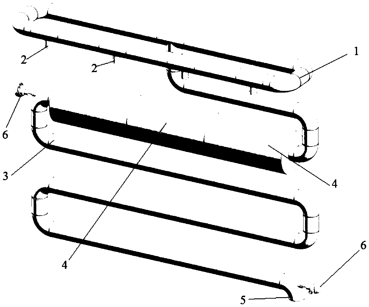
[0058] figure 1 A schematic structural diagram of a pipeline gasification device according to an embodiment of the present invention is shown.

[0059] The pipeline gasification device of this embodiment is used in the production process of coal-to-methane gas. In this process, after the primary preparation of methane gas, the generated methane gas and insufficiently reacted mixed gas are sent to the gasification system of the present invention. Pipeline gasification device, further gasification reaction, increase methane yield.

[0060] Such as figure 1 As shown, the pipeline gasification device includes:

[0061] An annular pipeline 1, on which a plurality of inlets 2 are equidistantly arranged;

[0062] A reaction pipeline 3, the reaction pipeline 3 is communicated with the annular pipeline 1, and the other end of the reaction pipeline 3 is provided with an air outlet 5;

[0063] Multiple sets of heating jackets 4, the heating jackets 4 are set on the reaction pipeline ...

Embodiment 2

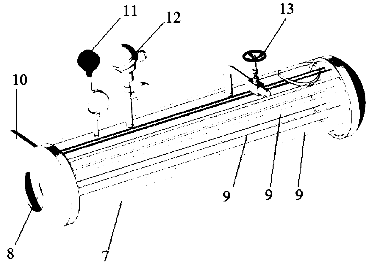
[0069] figure 1 A schematic structural diagram of a pipeline gasification device according to an embodiment of the present invention is shown. figure 2 A schematic structural diagram of a cooling tank according to an embodiment of the present invention is shown.

[0070] Such as Figure 1-Figure 2 As shown, the pipeline gasification device includes:

[0071] An annular pipeline 1, a plurality of inlets 2 are arranged at equal intervals on the annular pipeline 1;

[0072] A reaction pipeline 3, the reaction pipeline 3 is connected to the annular pipeline 1, and the other end of the reaction pipeline 3 is provided with an air outlet 5;

[0073] Multiple sets of heating jackets 4, 4 sets of heating jackets are set on the reaction pipeline 3;

[0074] The temperature sensor 6 and the pressure sensor, the temperature sensor 6 and the pressure sensor are arranged on the reaction pipeline 3;

[0075] The controller controls the heating jacket 4 to work according to the temperat...


PUM

PropertyMeasurementUnit
Lengthaaaaaaaaaa

Abstract

The invention provides a pipeline type gasification device. The pipeline type gasification device comprises an annular pipeline, a reaction pipeline and one or more sets of heating sleeves, at least one inlet is formed in the annular pipeline; one end of the reaction pipeline communicates with the annular pipeline, and the other end of the reaction pipeline is provided with an air outlet; the heating sleeves are arranged on the reaction pipeline in a sleeving mode. According to the pipeline type gasification device, the reaction space can be fully utilized, the reaction stroke is increased, the reaction temperature and the reaction pressure can be accurately controlled.

Description

technical field [0001] The invention belongs to a reaction device, and more specifically relates to a pipeline gasification device. Background technique [0002] my country's domestic natural gas production capacity is limited and cannot meet the rapid growth of domestic demand. Therefore, imported gas sources still account for a large weight in my country's natural gas consumption structure. In 2018, the national natural gas production was 107.7 billion cubic meters, the consumption was 147.1 billion cubic meters, and the gap between supply and demand reached 39.4 billion cubic meters. From January to April 2013, my country's natural gas production was 40.2 billion cubic meters, an increase of 7.7% year-on-year, and imports were about 17.1 billion cubic meters, an increase of 32.3%. The substantial increase in imported gas sources shows that the current domestic gas source supply still cannot keep up with demand pace of growth. The apparent consumption of natural gas in th...

Claims


Application Information

Patent Timeline
IPC IPC(8): F17D3/01
CPCF17D3/01
Inventor 王忠胜
Owner 中国煤层气集团有限公司
Features
  • R&D
  • Intellectual Property
  • Life Sciences
  • Materials
  • Tech Scout
  • Unparalleled Data Quality
  • Higher Quality Content
  • 60% Fewer Hallucinations
Learn More