
A liquid-cooled battery thermal management system and its control method

A thermal management system, liquid-cooled battery technology, applied in the direction of secondary batteries, circuits, electrical components, etc., can solve the problems of affecting battery cycle life, longer charging time, and rapid temperature rise of battery charging, so as to promote market application , improve environmental adaptability, optimize the effect of thermal management

Active Publication Date: 2020-07-17
ZHONGTONG BUS HLDG
View PDF1 Cites 0 Cited by
  • Summary
  • Abstract
  • Description
  • Claims
  • Application Information

AI Technical Summary

Problems solved by technology

With the improvement of battery energy density, during the use of electric vehicles, the above thermal management methods cannot completely solve the problem that the complex temperature environment affects battery performance
Moreover, these thermal management methods have low efficiency and poor effect, which is not conducive to the popularization and application of high energy density batteries in electric vehicles.
The charging temperature of the battery rises quickly, and the high temperature causes the charging current to drop, and then the charging time becomes longer, and the long-term high temperature use will affect the cycle life of the battery
If the battery is seriously overheated, it may even lead to thermal runaway of the battery

Method used


Image

  • A liquid-cooled battery thermal management system and its control method
  • A liquid-cooled battery thermal management system and its control method
  • A liquid-cooled battery thermal management system and its control method

Examples


Embodiment Construction

[0039] The present disclosure will be further described below in conjunction with the accompanying drawings and embodiments.

[0040] It should be noted that the following detailed description is exemplary and intended to provide further explanation of the present disclosure. Unless defined otherwise, all technical and scientific terms used herein have the same meaning as commonly understood by one of ordinary skill in the art to which this disclosure belongs.

[0041] It should be noted that the terminology used herein is only for describing specific embodiments, and is not intended to limit the exemplary embodiments according to the present disclosure. As used herein, unless the context clearly dictates otherwise, the singular is intended to include the plural, and it should also be understood that when the terms "comprising" and / or "comprising" are used in this specification, they mean There are features, steps, operations, means, components and / or combinations thereof.

...


PUM


Abstract

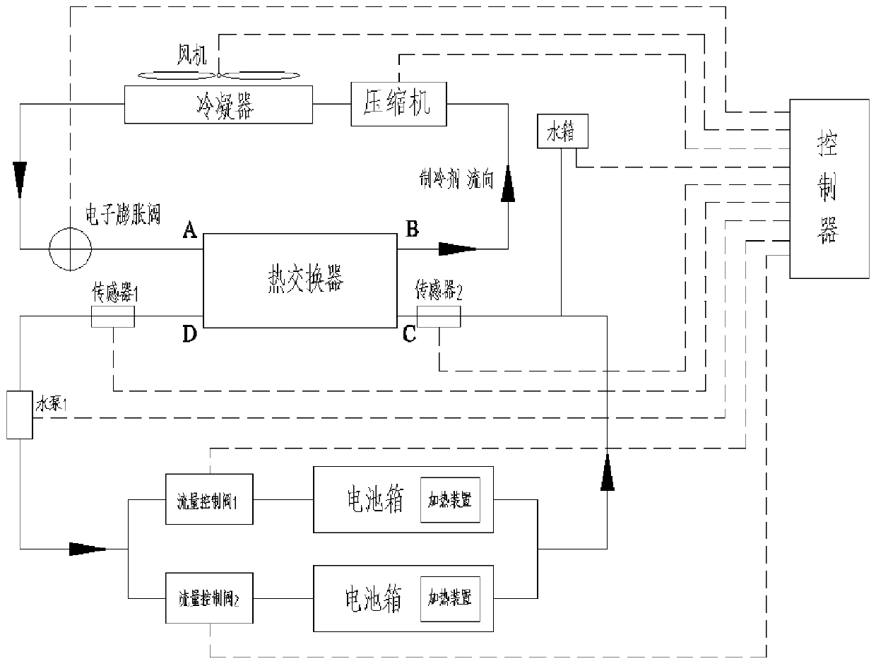
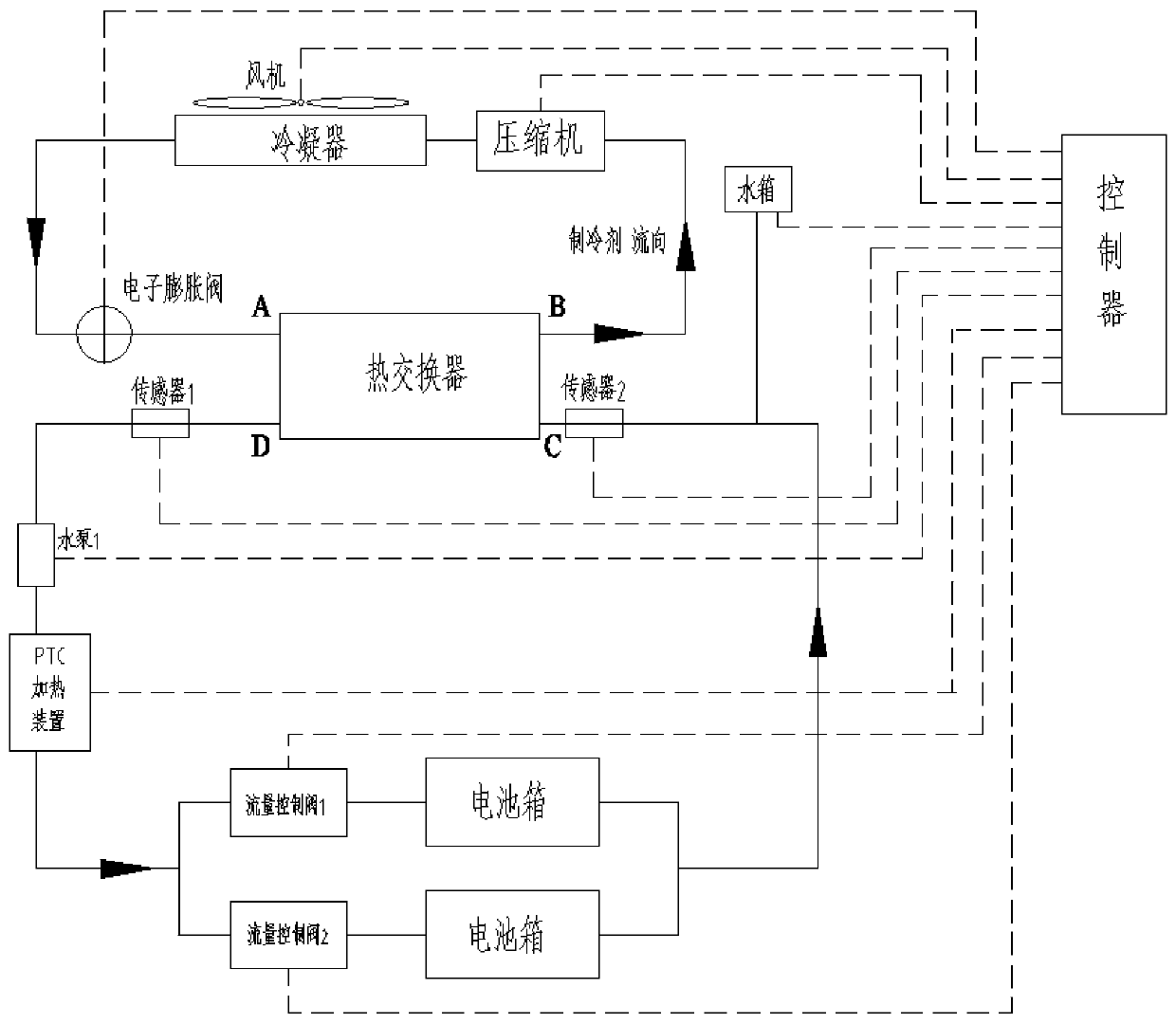
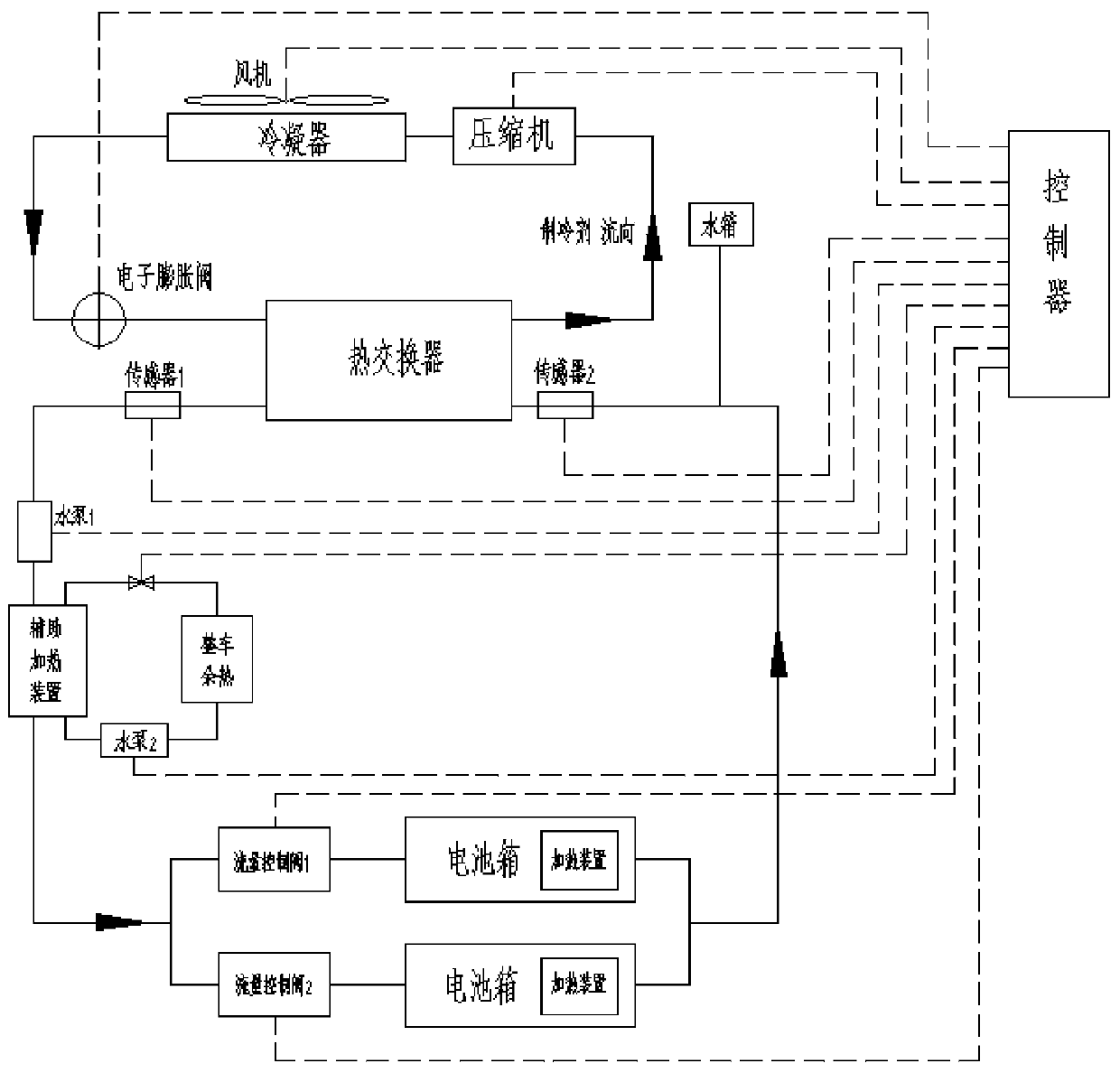
The disclosure provides a liquid-cooled battery thermal management system and its control method, including a controller, a refrigeration circuit, and a battery temperature control circuit. The refrigeration circuit includes a compressor, a condenser, and a heat exchanger. The outlet B of one end of the heat exchanger passes through The pipeline is connected to the compressor, the compressor is connected to the condenser through the pipeline, and the outlet of the condenser is connected to the inlet A of one end of the heat exchanger through the pipeline; the battery temperature control circuit includes several liquid-cooled battery boxes, sensors and heaters, and the heat exchanger The outlet D at one end of the exchanger is connected to the heater through a pipeline, and the outlet of the heater is divided into several branches through the pipeline, and each branch is controlled by a separate flow control valve and connected to the corresponding liquid-cooled battery box. One end, the other end of the liquid-cooled battery box is connected to the inlet C of the heat exchanger through pipelines; temperature sensors are installed at the outlet D and inlet C of the heat exchanger; the controller receives the signal collected by the temperature sensor and communicates with the compressor Machine, condenser, flow control valve and heater are electrically connected.

Description

technical field [0001] The present disclosure relates to a liquid-cooled battery thermal management system and a control method thereof. Background technique [0002] The statements in this section merely provide background information related to the present disclosure and do not necessarily constitute prior art. [0003] With the rapid development of the electric vehicle industry at home and abroad in recent years, the demand for electric vehicles to increase the energy density of power batteries is getting higher and higher. How to ensure the thermal safety of batteries under high energy density and further improve the environmental applicability of power batteries is the focus of research in the field of battery thermal management for electric vehicles. [0004] According to the knowledge of the inventors, at present, air cooling or natural cooling is mostly used for battery thermal management. With the improvement of battery energy density, the above thermal management...

Claims


Application Information

Patent Timeline
Patent Type & Authority Patents(China)
IPC IPC(8): H01M10/613H01M10/615H01M10/625H01M10/635H01M10/6567
CPCH01M10/613H01M10/615H01M10/625H01M10/635H01M10/6567Y02E60/10
Inventor 囤金军范志先董开雷吕平平于如兴刘涛
Owner ZHONGTONG BUS HLDG
Learn More