Oil-gas separation device which is arranged outside automobile fuel tank

A separation device and fuel tank technology, applied in the direction of power devices, separation methods, liquid degassing, etc., can solve the problems of high cost and inconvenient installation, and achieve reduced production and processing costs, convenient overall operation, and ingenious overall design Effect

Pending Publication Date: 2019-07-26
YAPP AUTOMOTIVE PARTS
View PDF0 Cites 0 Cited by
  • Summary
  • Abstract
  • Description
  • Claims
  • Application Information

AI Technical Summary

Problems solved by technology

In addition, most of the oil-gas separation devices currently used in the market are blow-molded or fixed inside the fuel tank, which is expensive and inconvenient to install.

Method used


Image

  • Oil-gas separation device which is arranged outside automobile fuel tank
  • Oil-gas separation device which is arranged outside automobile fuel tank
  • Oil-gas separation device which is arranged outside automobile fuel tank

Examples


Embodiment 1

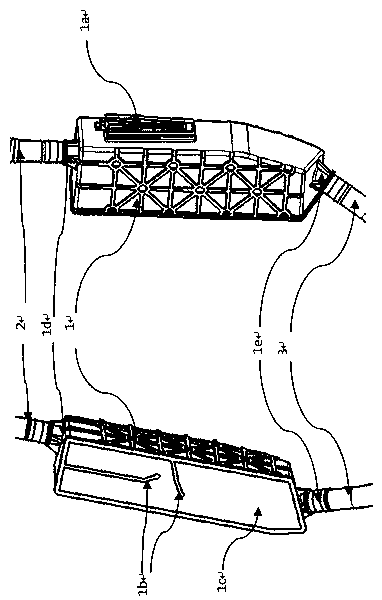
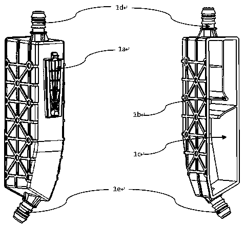
[0021] Embodiment 1: see Figure 1-Figure 7 , an oil-air separation device with an external fuel tank of an automobile, the oil-air separation device includes a main body 1 and an upper connecting pipeline 2 and a lower connecting pipeline 3 arranged at both ends of the main body 1, and the main body 1 includes a buckle fixing structure 1a, grid structure 1b, sealing cover plate 1c, and oil and gas inlet and outlet channels 1d and 1e, the buckle structure 1a, internal grille 1b, oil and gas inlet and outlet channels are integrally injection molded with the body 1, and the sealing cover plate 1c is welded and fixed In body 1. The overall shape of the cover coincides with the welding surface of the oil-gas separation body. There are a number of limit protrusions on the inside of the cover to facilitate the welding and positioning of the cover and the body, and the protrusions and the cover are integrally formed by injection molding. The oil-air separation device is set outside ...


PUM


Abstract

The invention relate to an oil-gas separation device which is arranged outside an automobile fuel tank, and is characterize in that the the oil-gas separation device comprises a body (1), an upper connecting pipeline (2) and a lower connecting pipeline (3) which are arranged at both ends of the body (1), wherein the body (1) comprises a buckle fixing structure (1a), a grid structure (1b), a sealing cover plate (1c) and oil-gas inlet and outlet channels (1d) (1e); the buckle structure (1a), the internal grid (1b), the oil and gas inlet and outlet channels (1d) (1e) and the body (1) are integrally molded; and the sealing cover plate (1c) is welded and fixed in the body (1). The technical scheme is ingenious in overall design and compact in structure; the scheme is formed by injection molding, so that the production and processing cost of the product is reduced; the oil-gas separation device is arranged outside the fuel tank and is assembled beside a fuel filler pipe, so that the internalspace of the fuel tank is effectively released; and the overall operation is convenient, so that the later maintenance is facilitated.

Description

technical field [0001] The invention relates to an oil-gas separation device, in particular to an oil-gas separation device externally placed in an automobile fuel tank, and belongs to the technical field of fuel tank structural components. Background technique [0002] During the process of fuel filling system, the gas in the fuel tank enters the fuel exhaust pipe through the valve, and then enters the carbon tank. On the one hand, it is necessary to prevent the internal pressure of the fuel tank from being too high, causing refueling problems such as refueling reverse injection, and on the other hand, to prevent the fuel leaking from the valve from directly entering the carbon tank and causing the breakdown of the carbon tank. In addition, most of the oil-gas separation devices currently on the market are blow-molded or fixed inside the fuel tank, which is expensive and inconvenient to install. For emission requirements, in addition to the low emission requirements for th...

Claims


Application Information

Patent Timeline
IPC IPC(8): B01D19/00B60K15/03
CPCB01D19/0042B60K15/03B60K2015/03328
Inventor 姜林刘亮吕昊杨杰严玲窦海伦张大康徐良清王艳辉
Owner YAPP AUTOMOTIVE PARTS
Why Eureka
Try Eureka