Prefabricated type cantilever retaining wall by grouting anchoring connecting method

A technology of prefabricated assembly and connection, applied in construction, artificial islands, infrastructure engineering, etc., can solve the problems of low transportation efficiency, complex on-site operation, low prefabrication rate, etc., to save installation and maintenance time and formwork turnover High efficiency and convenient prefabrication

Pending Publication Date: 2019-07-26
SHANGHAI MUNICIPAL ENG DESIGN INST GRP +2
View PDF7 Cites 8 Cited by
  • Summary
  • Abstract
  • Description
  • Claims
  • Application Information

AI Technical Summary

Problems solved by technology

At present, the prefabricated retaining wall used in the national standard atlas has its upper structure (panels and ribs) prefabricated in factories, but the floor structure is still constructed on site. This method of prefabricating the upper structure is more troublesome and the transportation efficiency is not high. (with ribs), the prefabrication rate is low, the maintenance time is long, and the on-site operation is relatively complicated

Method used


Image

  • Prefabricated type cantilever retaining wall by grouting anchoring connecting method
  • Prefabricated type cantilever retaining wall by grouting anchoring connecting method
  • Prefabricated type cantilever retaining wall by grouting anchoring connecting method

Examples


Embodiment Construction

[0031] The prefabricated cantilever retaining wall proposed by the present invention will be further described in detail below in conjunction with the accompanying drawings and specific embodiments. The advantages and features of the present invention will become clearer from the following description. The technical content and features of the present invention will be described in detail below by referring to the illustrated embodiments in conjunction with the accompanying drawings. It should be further noted that all the drawings are in very simplified form and use imprecise scales, and are only used to facilitate and clearly assist the purpose of illustrating the embodiments of the present invention.

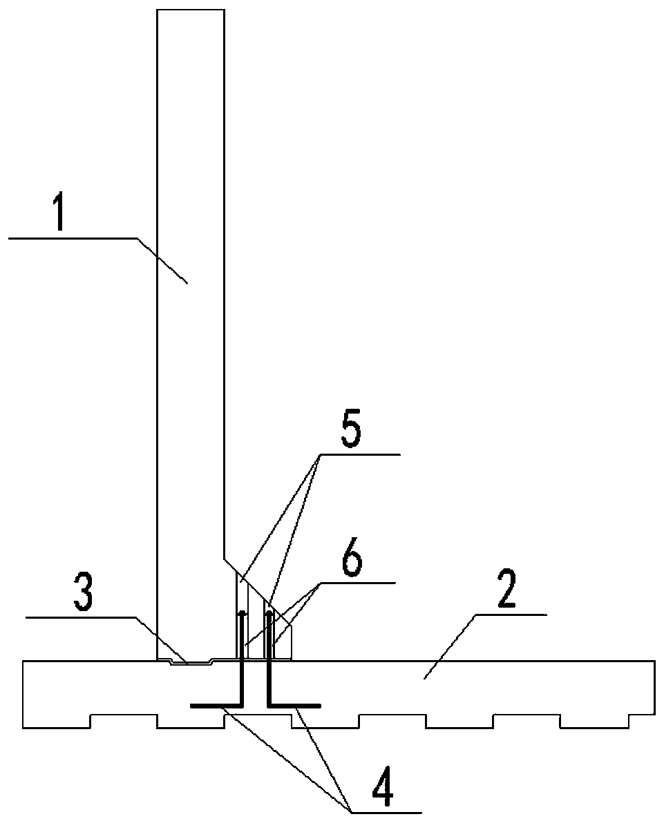
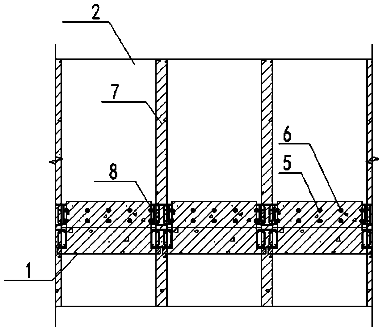
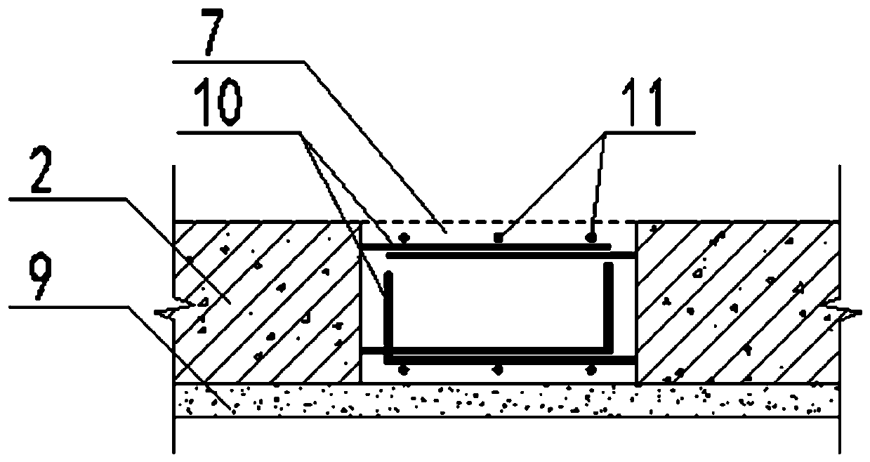
[0032] Combine below Figure 1~Figure 4 The connection and structural composition of the prefabricated cantilever retaining wall of the present invention will be described in detail.

[0033] In the figure: 1-prefabricated panel; 2-prefabricated bottom plate; 3-sitting grou...


PUM


Abstract

The invention provides a prefabricated type cantilever retaining wall by a grouting anchoring connecting method. The prefabricated type cantilever retaining wall is spliced by a plurality of sectionsof retaining wall segments, the retaining wall segments comprises prefabricated bottom plates and prefabricated surface plates, the prefabricated bottom plates are internally provided with pre-buriedvertical reinforced steel bars, reserved holes which are matched with the pre-buried vertical reinforced steel bars are formed in the prefabricated surface plates, and a bed mortar material is paved on the prefabricated bottom plates; and the prefabricated vertical reinforced steel bars of the prefabricated bottom plates penetrate through the reserved holes of the prefabricated surface plates, a grouting material is poured in the reserved holes to enabled the surface plates and the bottom plates to be connected into an integral structure, and vertical connection among the segments of the retaining wall is connected through post-pouring joints of the surface plates and the bottom plates. According to the prefabricated type cantilever retaining wall by the grouting anchoring connecting method, prefabrication in a factory, transportation and installation on site are facilitated, the workloads of the connection of the reinforced steel bars on the site and pouring of concrete are reduced, and the construction periods of the retaining wall is shortened; and the connecting strength and stability of a wall body can be ensured, the connection is reliable, the structure is simple, the construction is convenient, the quality of the connection of prefabricated components is easy to ensured, and the prefabricated type cantilever retaining wall has good popularization value.

Description

technical field [0001] The invention relates to the technical field of road engineering prefabrication and assembly, in particular to a disassembly and connection method of a prefabricated cantilever retaining wall, in particular to a prefabricated cantilever retaining wall adopting a grouting anchor connection method. Background technique [0002] Conventional cantilever retaining walls are basically cast-in-place, but the concrete strength of the wall is low and the amount of reinforcement is high; the amount of formwork is large, the turnover rate is low, and the construction efficiency is low; the construction site requires a lot of labor and labor costs; the process Complexity, slow construction speed, on-site maintenance and other issues. [0003] The conventional cantilever retaining wall adopts a section of 10m, the shape of the section is "L-shaped", the length is 10m, the width of the bottom plate is 4~5m, the height is 2~5m, and the maximum weight is 80 tons. If i...

Claims


Application Information

Patent Timeline
Patent Type & Authority Applications(China)
IPC IPC(8): E02D29/02
CPCE02D29/0283E02D2300/002
Inventor 袁胜强华锋赵勇毛由田朱婧颖冯宝金忠良沈伟高晓飞林景赐
Owner SHANGHAI MUNICIPAL ENG DESIGN INST GRP
Why Eureka
Try Eureka