Bolting plug-in vertical prefabricated shear wall and superimposed sheet joint structure and construction method thereof

A prefabricated shear force and plug-in technology, which is applied in the direction of building structure, floor slabs, building components, etc., can solve the problems of large construction impact, affecting construction progress, poor seismic performance, etc., to achieve improved bearing capacity and seismic ductility, and fast connection Convenience and the effect of improving shear performance

Active Publication Date: 2019-07-26
FUJIAN UNIV OF TECH
View PDF10 Cites 6 Cited by
  • Summary
  • Abstract
  • Description
  • Claims
  • Application Information

AI Technical Summary

Problems solved by technology

This connection method requires grouting on site, which has a great impact on construction and complicated procedures. The steel bars of the shear wall are not all connected, but connected at intervals. It takes time to construct the upper shear wall, which affects the construction progress
[0006] In the past, there were some studies on upper and lower prefabricated shear walls, but most of them did not consider the connection of floors, which is unrealistic. If the upper and lower prefabricated shear walls are only connected by steel bolts, this method may be damaged due to the bolt resistance under earthquake action. failure due to insufficient shear strength, and joints may fail prematurely due to insufficient strength or ductility
In addition, after the dry connection of the upper and lower prefabricated shear walls, it is difficult to achieve a reliable connection between the floor and the prefabricated shear walls

Method used


Image

  • Bolting plug-in vertical prefabricated shear wall and superimposed sheet joint structure and construction method thereof
  • Bolting plug-in vertical prefabricated shear wall and superimposed sheet joint structure and construction method thereof
  • Bolting plug-in vertical prefabricated shear wall and superimposed sheet joint structure and construction method thereof

Examples


Embodiment Construction

[0041] In order to make the above-mentioned features and advantages of the present invention more comprehensible, the following specific embodiments are described in detail with reference to the accompanying drawings.

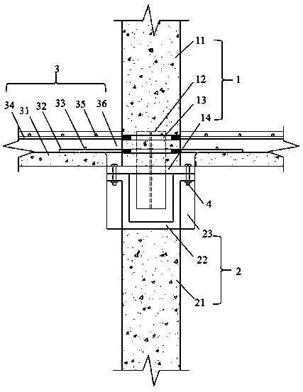
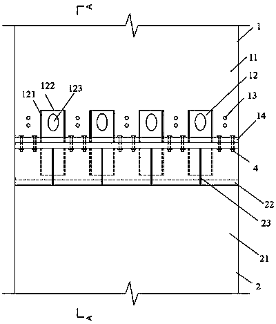
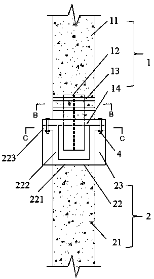
[0042] The connection structure between the upper and lower prefabricated shear walls and laminated slabs of the present invention is composed of an upper prefabricated shear wall 1, a lower prefabricated shear wall 2 and a floor 3, and the upper prefabricated shear wall 1 is composed of an upper prefabricated reinforced concrete wall 11. It consists of pre-embedded H-shaped steel 12, pre-embedded steel bar casing 13 and end plate 14. The pre-embedded H-shaped steel 12 is composed of two flanges 121 and a web 122, and the web 122 has H-shaped steel holes at the design position 123, the web 122 is located in the middle of the two flanges 121, forming an H shape, which can be welded or rolled, the surface of the web 122 is parallel to the surface of the upper pref...


PUM


Abstract

The invention relates to a bolting plug-in vertical prefabricated shear wall and superimposed sheet joint structure and a construction method thereof, which are characterized in that the bolting plug-in vertical prefabricated shear wall and superimposed sheet joint structure includes a lower prefabricated shear wall 2, an upper prefabricated shear wall 1 inserted to the top of the lower prefabricated shear wall 2, and floors 3 supported on both sides of the top of the lower prefabricated shear wall 2; the upper prefabricated shear wall 1 includes an upper prefabricated reinforced concrete wall11, H-shaped steel 12 pre-buried in the upper prefabricated reinforced concrete wall 11, a pre-buried steel casing pipe 13, and an end plate 14 arranged at the lower end portion of the upper prefabricated reinforced concrete wall 11; and according to the bolting plug-in vertical prefabricated shear wall and superimposed sheet joint structure and the construction method thereof, the connection isfast and reliable, the construction is convenient, the shear bearing capacity is high, seismic ductility and integrity are good, and the bolting plug-in vertical prefabricated shear wall and superimposed sheet joint structure with refrained concrete at the joint part and the construction method thereof are provided.

Description

[0001] Technical field: [0002] The invention belongs to the technical field of prefabricated assembled structures in civil engineering, and in particular relates to a connection structure and a construction method of a bolt-connected insertion type upper and lower prefabricated shear walls and laminated plates. [0003] Background technique: [0004] The prefabricated prefabricated structure has a series of advantages, and it is a structure worthy of vigorous promotion; the prefabricated shear wall structure is an important structure in the prefabricated structure, and has been used in engineering. The upper and lower prefabricated shear walls and the relationship between the shear wall and the floor The connection technology between them is the key issue in construction. [0005] The current construction method for the upper and lower connections of the prefabricated shear wall and the laminated slab is as follows: a certain length of steel bars are left on the upper part of...

Claims


Application Information

Patent Timeline
Patent Type & Authority Applications(China)
IPC IPC(8): E04B1/38E04B1/41E04B5/38
CPCE04B1/38E04B1/41E04B1/4114E04B1/4121E04B1/4142E04B5/38
Inventor 郑永乾陈阳升全晓祺朱睿周威苏文渊
Owner FUJIAN UNIV OF TECH
Why Eureka
Try Eureka