Cloth flaw detection control system on cloth spreading machine

A defect detection and control system technology, applied in the direction of spreading thin soft materials, analyzing materials, measuring devices, etc., can solve the problems of high labor intensity for workers, missing inspections, inaccurate inspections, etc., to improve spreading efficiency, Guarantee the pass rate and avoid the effect of high error rate

Inactive Publication Date: 2019-07-26
BULLMER ELECTROMECHANICAL TECH
View PDF11 Cites 10 Cited by
  • Summary
  • Abstract
  • Description
  • Claims
  • Application Information

AI Technical Summary

Problems solved by technology

However, there are still some problems: due to the manual inspection method, all the fabrics must be inspected once

Method used


Image

  • Cloth flaw detection control system on cloth spreading machine
  • Cloth flaw detection control system on cloth spreading machine
  • Cloth flaw detection control system on cloth spreading machine

Examples


Embodiment 1

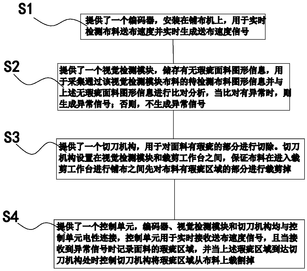
[0034] Such as figure 1 As shown, the cloth defect detection and control method on the spreading machine includes the following steps:

[0035] S1. An encoder is provided, which is installed on the cloth spreading machine, and is used to detect the cloth feeding speed of the cloth 1 in real time and generate a cloth feeding speed signal in real time.

[0036] Generally, an encoder is installed on the cloth spreading machine to detect the cloth feeding speed. Since the cloth has different materials, the requirements for the cloth feeding speed are different. The cloth of the same material is not always uniform during the whole cloth feeding process. , the speed is variable. The encoder can detect the current feeding speed of the cloth in real time to the control system of the spreading machine, so that the spreading machine can understand the current feeding speed of the cloth in real time for more accurate control. The detection principle is the existing technology and will n...

Embodiment 2

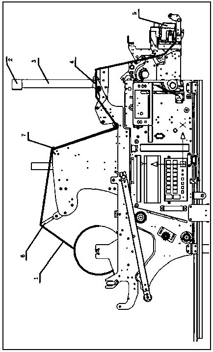
[0048] Such as figure 2 and 3 As shown, the cloth spreader includes a spreader rod 6 and a cloth feed rod 7. The blue line in the figure is the cloth. The cloth defect detection and control system on the cloth spreader includes:

[0049] The encoder is installed on the spreading machine and is used to detect the cloth feeding speed in real time and generate a cloth feeding speed signal in real time;

[0050] The visual inspection module stores the graphic information of the fabric with or without defects, and is used to collect the graphic information of the fabric to be inspected through the visual inspection module and compare and analyze it with the graphic information of the above-mentioned flawless fabric. When there is an abnormality in the comparison, an abnormality is generated signal; otherwise, no exception signal is generated;

[0051] The cutter mechanism 5 is used to cut off the defective part of the fabric;

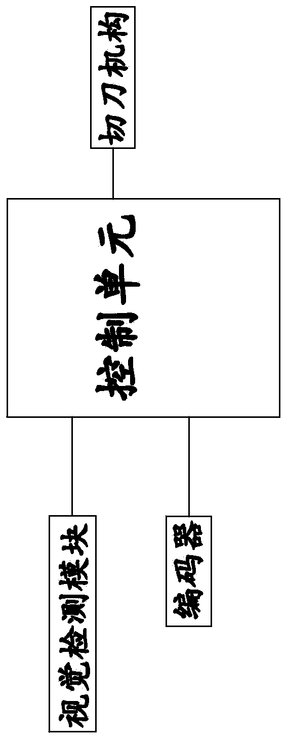
[0052] The control unit, the encoder, the visual d...


PUM


Abstract

The invention provides a cloth flaw detection control system on a cloth spreading machine and belongs to the field of cloth spreading machine control technologies. Through the system, the problems that in the prior art, cloth flaw detection efficiency is low, and accuracy is not high are solved. A cloth flaw detection control method comprises the steps that S1, an encoder is provided; S2, a visiondetection module is provided, wherein the vision detection module is used for collecting graphic information of to-be-detected cloth, performing comparative analysis and generating an anomaly signalwhen an anomaly is found through comparison; S3, a cutter mechanism is provided, wherein the cutter mechanism is used for cutting off a flawed part of the cloth; and S4, a control unit is provided, wherein the control unit is used for receiving a cloth-conveying velocity signal in real time, recording a flawed area of the cloth when receiving the anomaly signal and controlling the cutter mechanismto cut the flawed area off the cloth when the flawed area reaches the cutter mechanism. The cloth flaw detection control method has the advantages of high detection efficiency and high accuracy.

Description

technical field [0001] The invention belongs to the technical field of spreading machine control, and relates to a cloth defect detection and control system on a spreading machine. Background technique [0002] Spreading machine, a machine that aligns and lays rolls of jointless sewing materials layer by layer on the cutting table for cutting. There are two kinds of manual and automatic. The former has a simple structure and is manually pushed and pulled by the machine to spread the cloth back and forth; the latter is controlled by a computer and automatically performs operations such as spreading, cutting material (or continuous material), trimming and replacing cloth rolls, and recording the number of layers. The machine automatically stops working when the number of layers is set. [0003] Spreading machines generally include structures such as spreading rods, cloth feeding rods, cloth feeding rollers and cutting workbenches. The cloth roller enters the cutting table t...

Claims


Application Information

Patent Timeline
IPC IPC(8): G01N21/898B65H47/00
CPCB65H47/00G01N21/898
Inventor 项林辉肖科科陈建平
Owner BULLMER ELECTROMECHANICAL TECH
Why Eureka
Try Eureka