
Intelligent speed control system and intelligent speed control method for tunnel dynamic edge rate

An edge rate, tunnel technology, applied in the direction of road vehicle traffic control system, traffic control system, traffic signal control, etc., can solve the problems of reducing the average speed, fixed action interval, uncontrollable and so on

Active Publication Date: 2019-07-26
WUHAN UNIV OF TECH
View PDF10 Cites 3 Cited by
  • Summary
  • Abstract
  • Description
  • Claims
  • Application Information

AI Technical Summary

Problems solved by technology

[0004] Although the edge rate marking measures currently used to control vehicle speeding have obvious deceleration effects, their range of action is relatively fixed and cannot be controlled for real-time road conditions. In order to address the time-varying characteristics and individual differences of vehicle speed, a new speed control method needs to be proposed Measures, adopting different speed control schemes for vehicles in different speed ranges, can vary from vehicle to vehicle, control vehicle speed more efficiently and accurately, significantly reduce the variance of vehicle speed, and effectively reduce the average vehicle speed, both at the macro and micro levels. Significantly improve the level of road traffic safety

Method used


Image

  • Intelligent speed control system and intelligent speed control method for tunnel dynamic edge rate
  • Intelligent speed control system and intelligent speed control method for tunnel dynamic edge rate
  • Intelligent speed control system and intelligent speed control method for tunnel dynamic edge rate

Examples


Embodiment approach

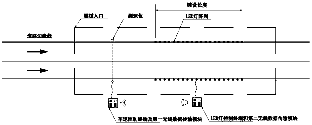
[0093] Combine below Figure 1 to Figure 3 Introduce the embodiment of the present invention, specifically:

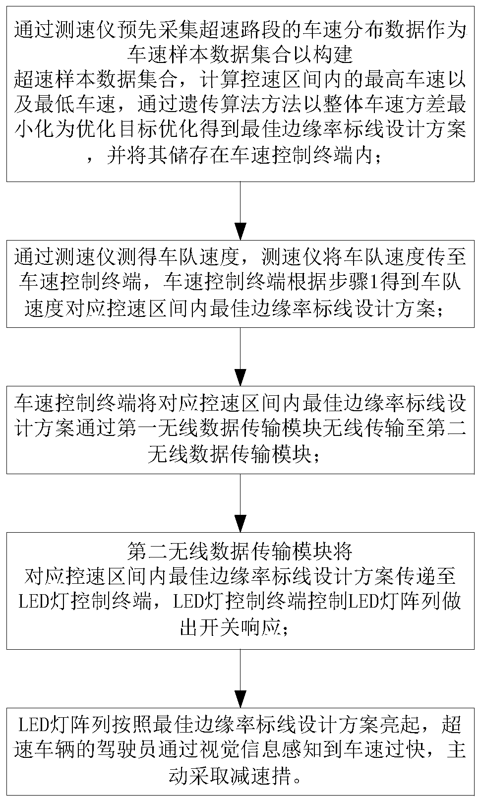
[0094] Step 1: Pre-collect the speed distribution data of the speeding road section through the speedometer as the speed sample data set to construct the speeding sample data set, calculate the highest speed and the lowest speed in the speed control interval, and use the genetic algorithm method to minimize the variance of the overall speed. Target optimization to obtain the best edge rate marking design scheme, that is, L r * and lambda r *, and store it in the vehicle speed control terminal.

[0095] The vehicle speed distribution data collected in advance by the speedometer in step 1 is as follows:

[0096] Select the tunnel with serious overspeed phenomenon as the implementation target, set up the speedometer in the long straight road section in the tunnel, and collect the vehicle speed data as the vehicle speed sample data set V 1 :

[0097]

[0098] Among...


PUM


Abstract

The invention discloses an intelligent speed control system and an intelligent speed control method for a tunnel dynamic edge rate. The intelligent speed control system comprises a distribution box, speed measuring instrument, a vehicle speed control terminal, a first wireless data transmission module, a second wireless data transmission module, an LED lamp control terminal and an LED lamp array.The intelligent speed control method comprises steps that vehicle speed distribution data of an overspeed road section is acquired in advance by a velocimeter, and is used as a vehicle speed sample data set, and an optimal marginal rate marking design scheme is acquired by using a genetic algorithm and minimizing an overall vehicle speed variance as an optimization target, and then the optimal marginal rate marking design scheme is recorded in a control terminal; a speed of a fleet is measured by the velocimeter, the velocimeter is used to transmit the speed of the fleet to the vehicle speed control terminal, and the vehicle speed control terminal is used to control the LED lamp array to make on-off response so as to implement the design scheme, and finally, the driver of the overspeed vehicle senses that the vehicle speed is too fast through visual information, and actively takes a deceleration measure. The invention is advantageous in that the dynamic response can be made according to the real-time driving state of the vehicle flow, and the driver can be prompted to control the driving speed actively, and therefore the difference of the vehicle flow speeds can be reduced, and thesafety level can be improved.

Description

technical field [0001] The invention belongs to the technical field of tunnel traffic safety, and in particular relates to a tunnel dynamic edge rate intelligent speed control system and method. Background technique [0002] When driving on the expressway, the driver will adapt to the perceived speed of the vehicle and underestimate the speed of the vehicle. This makes the driver often fail to take deceleration measures or decelerate insufficiently when driving into the tunnel, resulting in overspeed behavior. Insufficient lighting, poor line-of-sight guidance, limited sight distance of the driver, and speeding caused by misjudgment of speed increase the probability of accidents. [0003] According to the statistics of tunnel accidents, the death rate of tunnel accidents (the number of deaths caused by each accident) in the past five years is 0.48 per case, which is 1.6 times the death rate of all accidents in the same period. Among them, the death rate of expressway tunnel ...

Claims


Application Information

Patent Timeline
Patent Type & Authority Applications(China)
IPC IPC(8): G08G1/01G08G1/052G08G1/08
CPCG08G1/0141G08G1/052G08G1/08
Inventor 朱顺应刘兵卢华罗寅杰郑凯淘龚子任鲁哲贝润钊
Owner WUHAN UNIV OF TECH
Learn More