Charge storage device based on oxide nanoparticles formed by in-situ annealing, and preparation method thereof

A nanoparticle and charge storage technology, applied in the field of microelectronic materials, can solve the problems of low density of states and low storage density of devices

Inactive Publication Date: 2019-07-26
ANYANG NORMAL UNIV
View PDF0 Cites 1 Cited by
  • Summary
  • Abstract
  • Description
  • Claims
  • Application Information

AI Technical Summary

Problems solved by technology

However, due to the nitride (Si 3 N 4 ) The density of defect states in the storage layer is small, resulting in low storage density of the device

Method used


Image

  • Charge storage device based on oxide nanoparticles formed by in-situ annealing, and preparation method thereof
  • Charge storage device based on oxide nanoparticles formed by in-situ annealing, and preparation method thereof

Examples


Embodiment

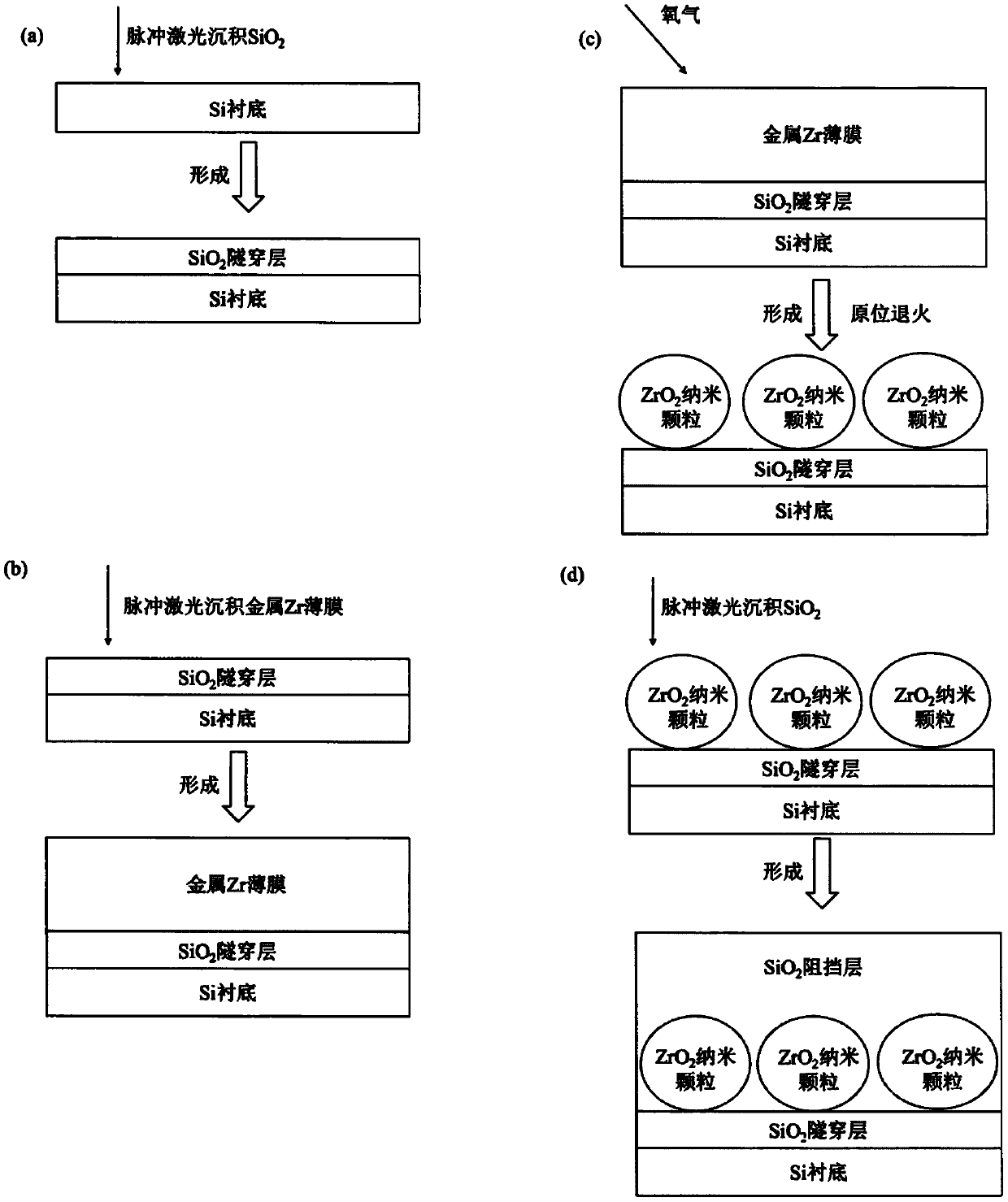
[0013] Example: In situ annealing to form ZrO 2 The preparation method of nanoparticle-based charge storage device is as follows:

[0014] a) Put the Si substrate in an appropriate amount of absolute ethanol, ultrasonically clean it for 3 minutes, and then ultrasonically clean it with deionized water for 1 minute to remove residual impurities on the surface of the Si substrate, and then put the substrate into a dilute hydrofluoric acid solution Immerse in the medium for 1 minute to remove oxides on the surface of the Si substrate, then ultrasonically clean it with deionized water for 2 minutes, dry it with high-purity nitrogen, and put it on the substrate table in the pulsed laser deposition chamber for thin film deposition;

[0015] b) SiO 2 The ceramic target is fixed on the target table in the pulsed laser deposition chamber, and then a layer of SiO is deposited on the surface of the Si substrate 2 The thin film acts as a tunneling layer, and the pressure in the chamber i...


PUM


Abstract

The invention discloses a charge storage device based on oxide nanoparticles formed by in-situ annealing, and a preparation method thereof. A layer of metal Zr thin film is grown by virtue of a pulsedlaser deposition method; and in-situ oxygen annealing treatment is carried out to form a ZrO2 nanoparticle storage medium. The preparation method of the charge storage device based on the ZrO2 nanoparticles formed by the in-situ annealing is simple in operation and can realize large-scale preparation.

Description

technical field [0001] The invention belongs to the field of microelectronic materials, and relates to a preparation method for an oxide nanoparticle-based charge storage device formed by in-situ annealing. Background technique [0002] As the feature size of non-volatile charge storage devices gradually decreases, floating gate charge trap storage devices face physical and technical bottlenecks, mainly due to the continuous reduction in the size of the tunneling layer, serious charge loss, and increased power consumption. To solve this problem, polysilicon-oxide-nitride-oxide-silicon (SONOS) type charge trap memory devices have been extensively studied. However, due to the nitride (Si 3 N 4 ) The density of defect states in the storage layer is small, resulting in low storage density of the device. Nanoparticles have higher surface defect states, which can significantly increase the storage density of devices. Based on the above considerations, we invented in-situ annea...

Claims


Application Information

Patent Timeline
Patent Type & Authority Applications(China)
IPC IPC(8): H01L27/11521
CPCH10B41/30
Inventor 汤振杰
Owner ANYANG NORMAL UNIV
Why Eureka
Try Eureka