Vacuumizing and liquid injection device

A liquid injection and vacuum technology, applied in the direction of secondary battery gas removal, electrical components, circuits, etc., can solve the problems of low vacuum efficiency, time-consuming, high time cost, etc., to ensure sealing, ensure position accuracy and Stability, quality-enhancing effects

Pending Publication Date: 2019-07-26
DONGGUAN CHAOYE PRECISION EQUIPMENT CO LTD
View PDF0 Cites 1 Cited by
  • Summary
  • Abstract
  • Description
  • Claims
  • Application Information

AI Technical Summary

Problems solved by technology

At present, most of the liquid injection for soft pack power batteries on the market is under normal pressure. This normal pressure liquid injection process will cause many bubbles inside the battery, which will seriously affect the quality of the battery and the consistency of the product; Injecting liquid under normal pressure, the electrolyte is difficult to absorb, and the absorption is uneven. The battery that needs liquid injection takes a lot of time in the process of liquid injection, the time cost is high, the production efficiency of the battery is low, and the market competitiveness of the product is seriously reduced.
In the prior art, there is also the method of vacuumizing the working space, and then injecting liquid into the battery air bag in the working space. Although this method realizes the injection of electrolyte solution into the battery air bag in a vacuum state, the structure of the existing equipment is complicated. , the efficiency of vacuuming the working space is low, the quality of vacuuming is poor, and it is difficult to guarantee the quality of battery production

Method used


Image

  • Vacuumizing and liquid injection device
  • Vacuumizing and liquid injection device
  • Vacuumizing and liquid injection device

Examples


Embodiment Construction

[0026] In order to facilitate the understanding of those skilled in the art, the present invention will be further described below in conjunction with the embodiments and accompanying drawings, and the contents mentioned in the embodiments are not intended to limit the present invention.

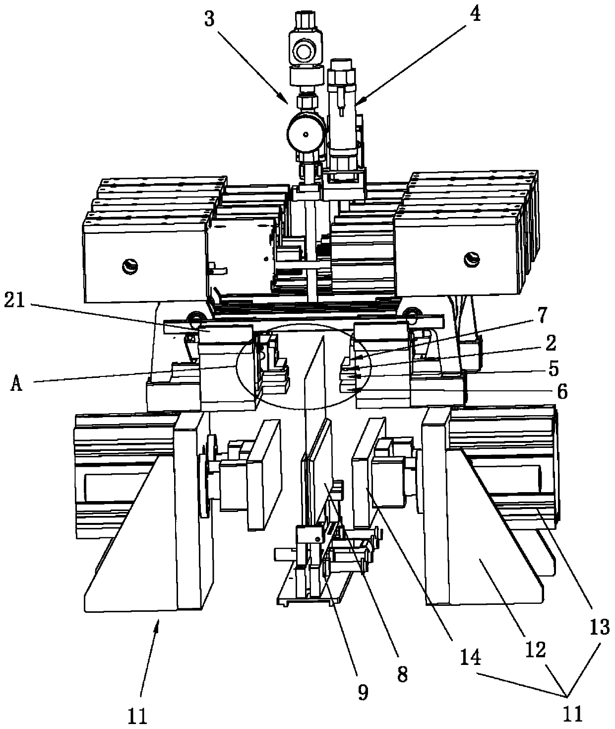
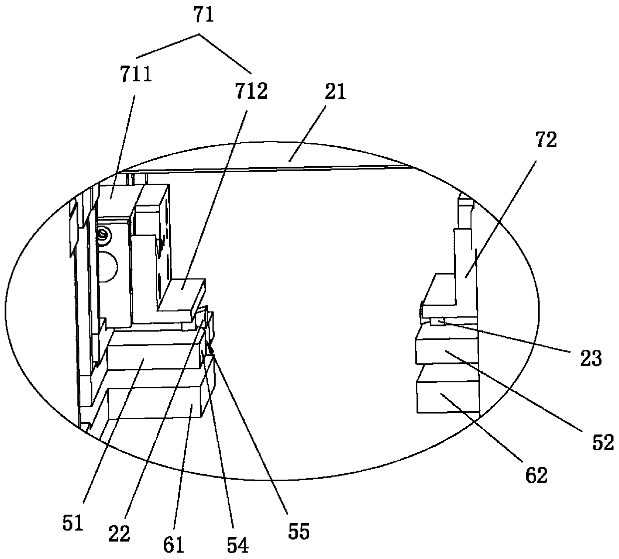
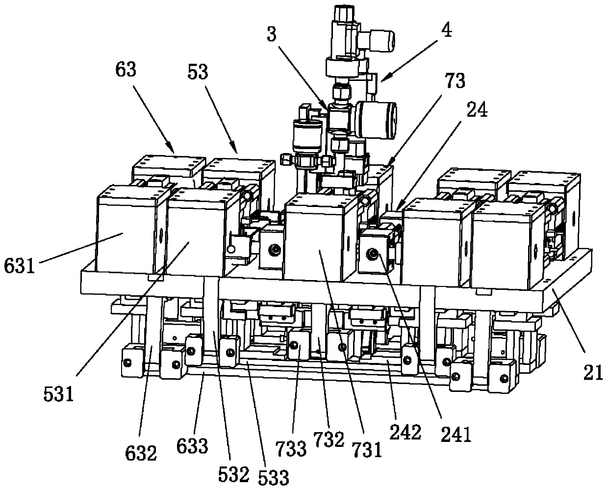
[0027] Such as Figure 1 to Figure 8 As shown, a vacuum liquid injection device provided by the present invention includes a clamping mechanism for clamping the main body of the battery, a bag opening mechanism 2 for opening the bag opening of the battery air bag, and a bag opening mechanism 2 for pumping the battery air bag. Vacuum liquid injection mechanism 3 for vacuuming and liquid injection, a lifting drive mechanism for driving the output end of the vacuum liquid injection mechanism 3 to insert or remove the pocket of the battery air bag 4, and a lifting drive mechanism for tightening the pocket of the battery air bag to A closing sealing mechanism 5 for sealing the gap between the bat...


PUM


Abstract

The invention relates to the technical field of battery production, in particular to a vacuumizing and liquid injection device. The vacuumizing and liquid injection device comprises a clamping mechanism used for clamping a battery main body, a bag opening mechanism used for opening a bag opening of a battery gas bag, a vacuumizing and liquid injection mechanism used for performing vacuumizing andliquid injection on the battery gas bag, a lifting driving mechanism used for driving the output end of the vacuumizing and liquid injection mechanism to be inserted into or moved out of the bag opening of the battery air bag, an opening closing and sealing mechanism used for tightening the bag opening of the battery gas bag for sealing the gap between the battery gas bag and the output end of thevacuumizing and liquid injection mechanism, a clamping and sealing mechanism used for clamping the bag opening of the battery gas bag after being subjected to vacuumizing and liquid injection, and asealing mechanism used for sealing the battery gas bag after clamping the bag opening. The vacuumizing and liquid injection device is stable in working and high in efficiency, and the vacuumizing andliquid injecting mechanism directly performs vacuum pumping and liquid injection on the battery gas bag, so that the efficiency of vacuumizing and liquid injection is improved, the production period is shortened, and the quality of battery production is also improved.

Description

technical field [0001] The invention relates to the technical field of battery production, in particular to a vacuum liquid injection device. Background technique [0002] Soft pack power battery is an industrial product in the field of new energy. It has the advantages of energy saving, environmental protection and environmental friendliness, and its application is becoming more and more extensive. The production process of the soft pack power battery involves injecting battery fluid into the battery that needs to be injected. At present, most of the liquid injection for soft pack power batteries on the market is under normal pressure. This normal pressure liquid injection process will cause many bubbles inside the battery, which will seriously affect the quality of the battery and the consistency of the product; Injecting liquid under normal pressure, the electrolyte is difficult to absorb, and the absorption is uneven. The battery that needs liquid injection takes a lot ...

Claims


Application Information

Patent Timeline
Patent Type & Authority Applications(China)
IPC IPC(8): H01M2/36H01M10/52H01M50/609H01M50/636
CPCH01M10/52H01M50/636H01M50/60Y02E60/10
Inventor 梁桂庆钟年生
Owner DONGGUAN CHAOYE PRECISION EQUIPMENT CO LTD
Why Eureka
Try Eureka