
Power cabinet mounting base for safety protection of electronic equipment

A technology for safety protection and electronic equipment, which is applied in substation/distribution device shells, anti-seismic equipment, electrical components, etc. It can solve the problems of low service life of internal components, large limitations, loose components, etc., and achieve strong anti-interference, Strong anti-vibration effect

Pending Publication Date: 2019-07-26
永春锐拓信息技术中心
View PDF0 Cites 5 Cited by
  • Summary
  • Abstract
  • Description
  • Claims
  • Application Information

AI Technical Summary

Problems solved by technology

[0002] At present, electronic information equipment is used in all walks of life, and because its software requires hardware support, special protection measures are required for electronic equipment, referred to as safety protection. Many power cabinets with electronic components are installed outdoors, but due to outdoor The instability of the surrounding environment leads to low service life of internal components, and it is prone to loose parts due to micro-vibration, which has relatively large limitations.

Method used


Image

  • Power cabinet mounting base for safety protection of electronic equipment
  • Power cabinet mounting base for safety protection of electronic equipment
  • Power cabinet mounting base for safety protection of electronic equipment

Examples


Embodiment Construction

[0020] The following will clearly and completely describe the technical solutions in the embodiments of the present invention with reference to the accompanying drawings in the embodiments of the present invention. Obviously, the described embodiments are only some, not all, embodiments of the present invention. Based on the embodiments of the present invention, all other embodiments obtained by persons of ordinary skill in the art without making creative efforts belong to the protection scope of the present invention.

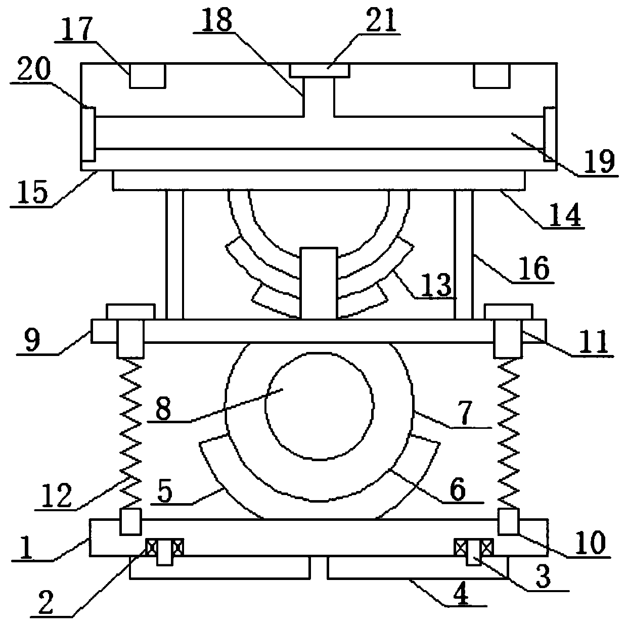
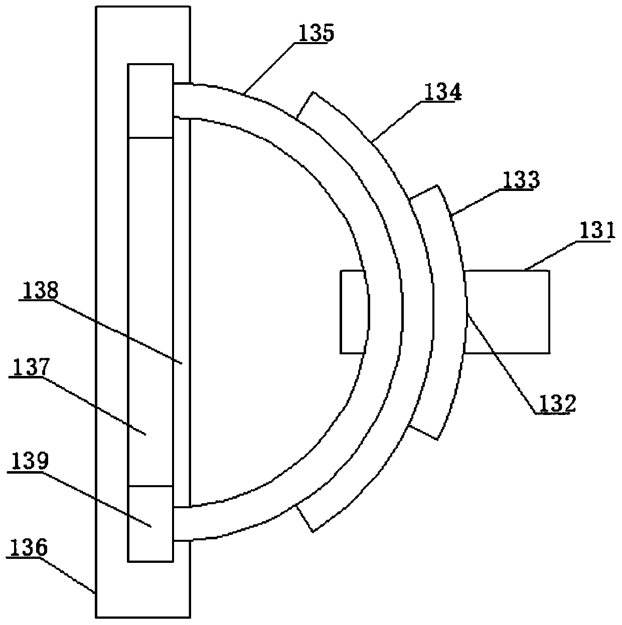
[0021] see figure 1 , an embodiment provided by the present invention: includes a bottom mounting substrate 1, a main bearing 2 is installed inside the bottom surface of the bottom mounting substrate 1, a first rotating shaft 3 is installed in the inner ring of the main bearing 2, and the The shaft body at the bottom end of the first rotating shaft 3 is installed inside the rotating plate 4, and the center of the upper surface of the bottom mounting substrate ...


PUM


Abstract

The invention discloses a power cabinet mounting base for safety protection of electronic equipment. The power cabinet mounting base comprises a bottom mounting base plate. According to the power cabinet mounting base, the power cabinet mounting base is installed on the ground through cement, and the horizontal angle adjusting effect can be realized through a three-point positioning technology, sothat the device can achieve a certain bending effect when being impacted by the outside, and is high in anti-interference performance; meanwhile, the device has a buffering function and is high in anti-vibration effect; moreover, the device is provided with a thread and spiral three-point positioning horizontal angle adjusting mechanism, the horizontal angle of the device can be effectively controlled by utilizing the thread structure and the spiral blades, and meanwhile, the device has an effect of resisting transverse external force; in addition, the device is provided with an annular steelplate accumulation incremental type friction energy consumption conversion mechanism, so that the vibration effect can be converted into friction, the heat energy is generated, and the energy consumption effect is realized; and in addition, the device is provided with a spiral spring telescopic buffering effective damping mechanism and can achieve a certain anti-vibration effect under the actionof a spiral spring.

Description

technical field [0001] The invention relates to the technical field of electronic safety protection, in particular to a power cabinet installation base for electronic equipment safety protection. Background technique [0002] At present, electronic information equipment is used in all walks of life, and because its software requires hardware support, special protection measures are required for electronic equipment, referred to as safety protection. Many power cabinets with electronic components are installed outdoors, but due to outdoor The instability of the surrounding environment leads to low service life of internal components, and it is prone to loose parts due to micro-vibration, which has relatively large limitations. Contents of the invention [0003] The object of the present invention is to provide a power cabinet installation base for electronic equipment safety protection, so as to solve the problems raised in the above-mentioned background technology. [000...

Claims


Application Information

Patent Timeline
Patent Type & Authority Applications(China)
IPC IPC(8): H02B1/30H02B1/54
CPCH02B1/303H02B1/54
Inventor 黄艳芬
Owner 永春锐拓信息技术中心
Learn More