Rotary electric device control device, and electric power steering device using same
A technology of rotating motors and control devices, which is applied in power steering mechanisms, electric steering mechanisms, AC motor control, etc., and can solve problems such as system mismatch
- Summary
- Abstract
- Description
- Claims
- Application Information
AI Technical Summary
Problems solved by technology
Method used
Image

Examples
no. 1 approach
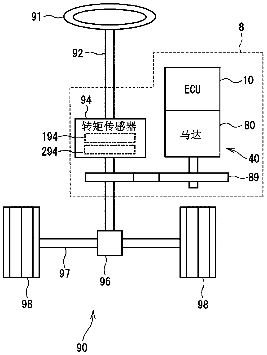
[0061] The first embodiment is shown in Figure 1 to Figure 11 . like figure 1 As shown, the ECU 10 as the rotating electrical machine control device of the present embodiment is applied to, for example, the electric power steering 8 for assisting the steering operation of the vehicle together with the motor 80 as the rotating electrical machine. figure 1 It is a diagram showing the overall configuration of a steering system 90 including the electric power steering device 8 .
[0062] figure 1 The configuration of a steering system 90 including the electric power steering device 8 is shown. The steering system 90 includes a steering wheel 91 as a steering member, a steering shaft 92 , a pinion 96 , a rack shaft 97 , wheels 98 , the electric power steering 8 , and the like. The steering wheel 91 is connected to a steering shaft 92 . A torque sensor 94 for detecting a steering torque Ts is provided on the steering shaft 92 . A pinion gear 96 is provided at the front end of...
no. 2 approach
[0138] The second embodiment is shown in Figure 12 as well as Figure 13 . In the second embodiment to the fifth embodiment and the seventh embodiment, since the control unit is different, the description will focus on this point. As shown in Figure 12, the first control unit 132 as the main control unit is the same as the first embodiment, and has a dq-axis current calculation unit 140, an assist torque command calculation unit 141, a q-axis current command calculation unit 142, a d-axis current The command calculation unit 143 , the first current feedback calculation unit 150 , the first three-phase voltage command calculation unit 161 , the first PWM calculation unit 163 , the first signal output unit 165 and the first communication unit 170 .
[0139] The second control unit 232 as the slave control unit includes the second dq axis current calculation unit 240, the second current feedback calculation unit 250, the second three-phase voltage command value calculation uni...
no. 3 approach
[0147] The third embodiment is shown in Figure 14 ~ Figure 16 . like Figure 14 As shown, the first control unit 133 as the main control unit has a dq-axis current calculation unit 140 , an assist torque command calculation unit 141 , a q-axis current command calculation unit 142 , a d-axis current command calculation unit 143 , and a current feedback calculation unit 175 , a first three-phase voltage command calculation unit 161 , a first PWM calculation unit 163 , a first signal output unit 165 , and a first communication unit 170 .
[0148] The current feedback calculation unit 175 performs current feedback calculation based on dq axis current command values Id*, Iq*, and dq axis current detection values Id1, Iq1, Id2, Iq2, and calculates dq axis voltage command values Vd1*, Vq1*, Vd2 *, Vq2*.
[0149] The second control unit 233 as a slave control unit includes a dq-axis current calculation unit 240 , a second three-phase voltage command value calculation unit 26...
PUM
 Abstract
Description
Claims
Application Information
 - R&D
- Intellectual Property
- Life Sciences
- Materials
- Tech Scout
- Unparalleled Data Quality
- Higher Quality Content
- 60% Fewer Hallucinations
Browse by: Latest US Patents, China's latest patents, Technical Efficacy Thesaurus, Application Domain, Technology Topic, Popular Technical Reports.
© 2025 PatSnap. All rights reserved.Legal|Privacy policy|Modern Slavery Act Transparency Statement|Sitemap|About US| Contact US: help@patsnap.com