Double-die head coating device and pole piece coating process thereof

A technology of coating device and coating process, which is applied to devices for coating liquid on surfaces, coatings, electrode manufacturing, etc. , the effect of reducing the risk of abnormality, improving production efficiency and production excellence rate

Pending Publication Date: 2019-07-30
HUIZHOU LIWINON NEW ENERGY TECH CO LTD
View PDF0 Cites 5 Cited by
  • Summary
  • Abstract
  • Description
  • Claims
  • Application Information

AI Technical Summary

Problems solved by technology

[0006] One of the purposes of the present invention is to provide a double-die coating device to solve the problem of low coating utilization rate of the existing electrode lug welding area in view of the deficiencies in the prior art

Method used


Image

  • Double-die head coating device and pole piece coating process thereof
  • Double-die head coating device and pole piece coating process thereof
  • Double-die head coating device and pole piece coating process thereof

Examples


Embodiment 1

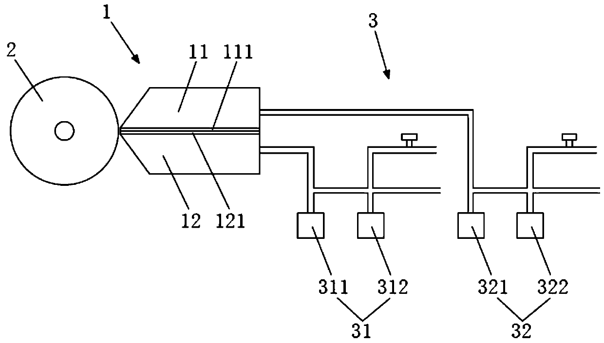
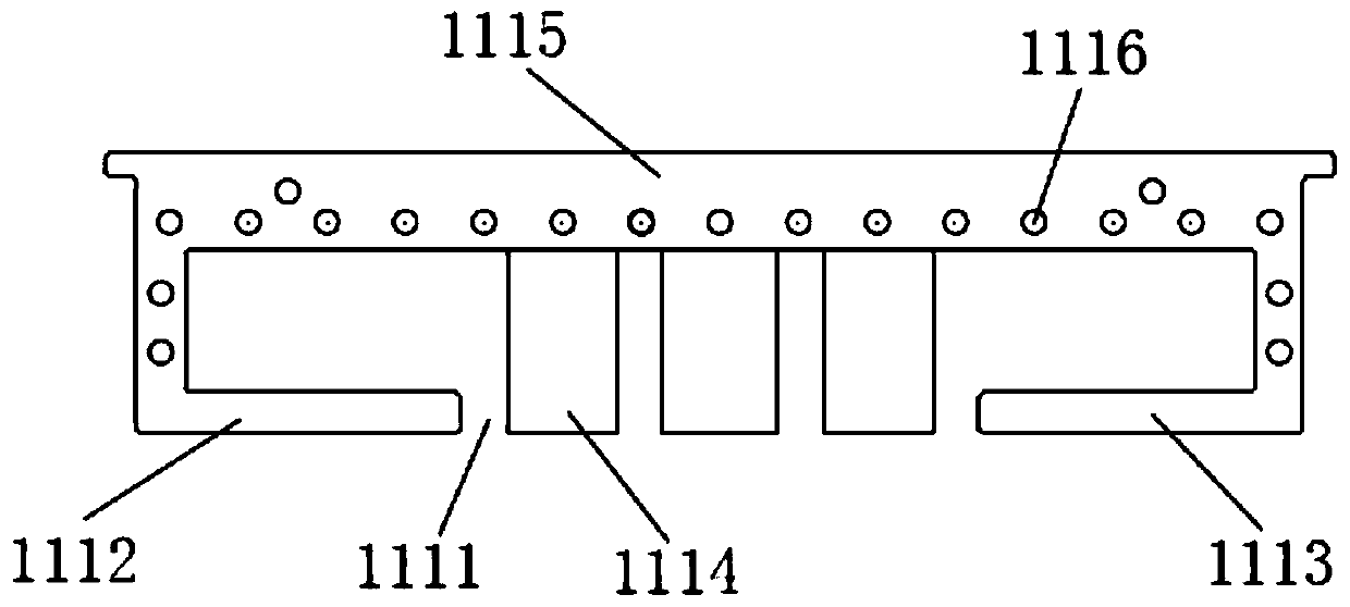
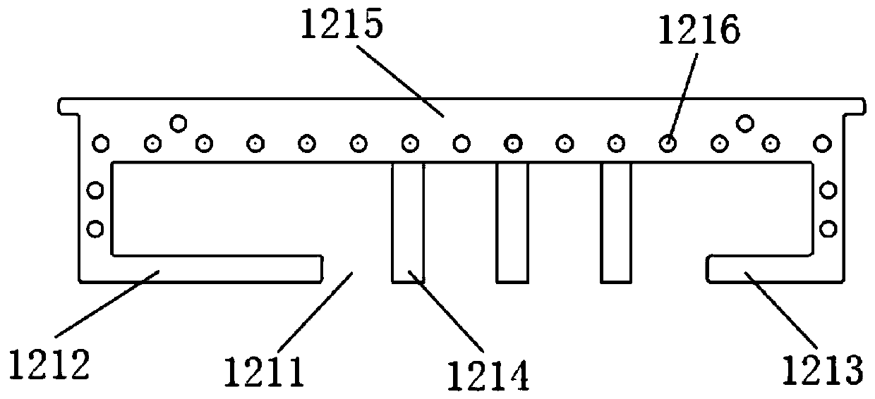
[0035] Such as Figure 1~5 As shown, a double die head coating device includes a die head structure 1 and a roller shaft structure 2 arranged in cooperation with the die head structure 1. The die head structure 1 includes a first die head 11 and a corresponding arrangement with the first die head 11. The second die head 12, the first die head 11 is provided with a first gasket 111, the second die head 12 is provided with a second gasket 121, the first gasket 111 and the second gasket 121 are correspondingly arranged on the first mold Between the head 11 and the second die head 12, wherein, the first gasket 111 is provided with a first fixing hole 1116, and is fixed on the first die head 11 by cooperating with screws, and the second gasket 121 is provided with a second The fixing hole 1216 is fixed on the second die head 12 by screwing with the screw; the first gasket 111 has a plurality of first flow openings 1111, the second gasket 121 has a plurality of second flow openings ...

Embodiment 2

[0046] A pole piece coating process of a double-die coating device, the double-die coating device is the double-die coating device of any one of the above-mentioned sections, and the pole piece coating process comprises in turn:

[0047] The first coating stage: the roller shaft structure 2 drives the pole piece 4 to rotate, and the first die head 11 and the second die head 12 coat the rotating pole piece 4 at the same time, and the coating is respectively drawn from multiple first flow ports 1111 and multiple A second flow port 1211 flows out, so that the pole piece 4 gets the first complete paint area 411 covered by the paint, and a plurality of first flow ports 1111 and a plurality of second flow ports 1211 correspond to obtain the first complete paint area 411;

[0048] Partial coating stage: the first die head 11 stops coating, the second die head 12 continues to coat the rotating pole piece 4, and the paint flows out from a plurality of second branch ports 1211, so that t...


PUM


Abstract

The invention belongs to the technical field of lithium ion battery preparation, and particularly relates to a double-die head coating device. The double-die head coating device comprises a die head structure and a roller shaft structure matched with the die head structure, wherein the die head structure comprises a first die head and a second die head correspondingly arranged with the first die head; the first die head is provided with a first gasket; the second die head is provided with a second gasket; the first gasket and the second gasket are correspondingly arranged between the first diehead and the second die head; the first gasket is provided with a plurality of first shunting ports; the second gasket is provided with a plurality of second shunting ports; and the first shunting ports and the second shunting ports are arranged in a staggered corresponding mode. Compared with the prior art, the first gasket and the second gasket are correspondingly arranged between the first diehead and the second die head, so that the die head structure obtains a lug welding area with high coating utilization rate, and finally a pole piece with high coating utilization rate of the lug welding area is obtained, the risk of abnormality of a battery product is reduced, and the production efficiency and the production yield are improved.

Description

technical field [0001] The invention belongs to the technical field of lithium ion battery preparation, and in particular relates to a double-die coating device. Background technique [0002] Lithium-ion batteries have the advantages of light weight and good safety performance, so they have been in a monopoly position in the application of mobile electronic devices such as Bluetooth headsets, mobile phones, notebook computers, tablet computers, cameras, and portable mobile power supplies. At the same time, lithium-ion batteries have also been applied in batches in electric motorcycles, electric vehicles and other fields. [0003] When the current lithium-ion battery is coating the pole piece, there will be a section of tab welding area at the head of the cell pole piece for welding the tab, and the tab welding area is an empty foil area. When the existing battery cells are formed, sorted and charged, the electrons at the tail of the pole piece need to move to the position o...

Claims


Application Information

Patent Timeline
Patent Type & Authority Applications(China)
IPC IPC(8): B05C1/06B05C1/16B05C11/10B05C13/02B05D1/00H01M4/04H01M10/0525
CPCB05C1/06B05C1/16B05C11/10B05C11/1044B05C13/02B05D1/005H01M4/0404H01M10/0525Y02E60/10
Inventor 张帅王润发纪荣进郑明清王威李载波杨山
Owner HUIZHOU LIWINON NEW ENERGY TECH CO LTD
Why Eureka
Try Eureka