
Cleaning robot

A technology for cleaning robots and bodies, applied in the field of cleaning robots, can solve the problems of residual water in the water tank, unable to fully seep out, inconvenient to use, etc., and achieve the effect of increasing water storage capacity, reducing the risk of abnormal water tank, and high cleaning efficiency

Pending Publication Date: 2020-09-22
ECOVACS ROBOTICS (SUZHOU ) CO LTD
View PDF9 Cites 0 Cited by
  • Summary
  • Abstract
  • Description
  • Claims
  • Application Information

AI Technical Summary

Problems solved by technology

Since the water flows to the mopping cloth through the seepage channel, if the pressure in the water tank is not enough, there will be residual water at the bottom of the water tank, which cannot be fully seeped out. Secondly, when taking out the water tank, it is necessary to turn the body over before taking it out, causing the water tank to The residual water in the interior is poured out, which is very inconvenient for users to use
[0004] The prior art with the application publication number of CN105662280A discloses that the fan assembly 16 and the water tank 1 are arranged side by side, resulting in a small capacity of the water tank and causing inconvenience to the user.

Method used


Image

  • Cleaning robot
  • Cleaning robot
  • Cleaning robot

Examples


Embodiment Construction

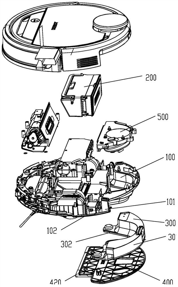
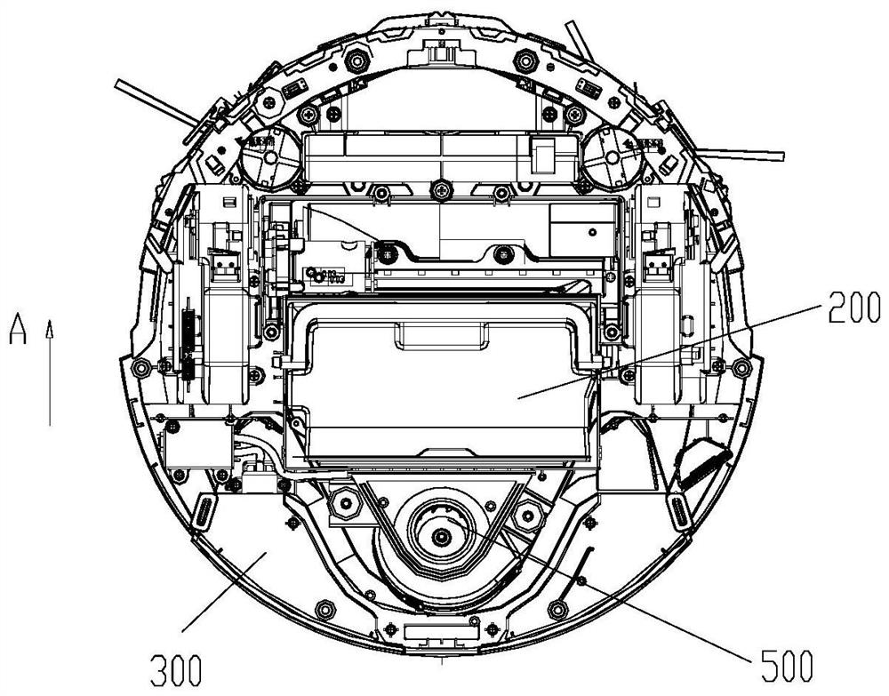
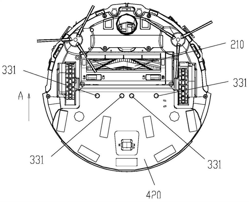
[0024] figure 1 It is an exploded view of the overall structure of the cleaning robot of the present invention; figure 2 It is one of the schematic diagrams of the bottom surface structure of the cleaning robot of the present invention; image 3 It is the second schematic diagram of the bottom surface structure of the cleaning robot of the present invention; Figure 4 It is a schematic diagram of the location of the water outlet pipeline of the present invention. Such as Figure 1 to Figure 4 As shown, the present invention provides a cleaning robot, including a body 100, on which a dust box 200, a water tank 300, and a fan assembly 500 are provided, and the bottom of the body 100 is provided with a dust suction port 210 connected to the dust box. figure 2 , image 3 As shown, assuming that the walking direction A of the cleaning robot is the front, the dust suction port 210, the dust box 200, the fan assembly 500 and the water tank 300 are sequentially arranged on the b...


PUM


Abstract

The embodiment of the invention provides a cleaning robot. The cleaning robot comprises a machine body, a water tank and a water outlet pipeline, wherein the water tank is detachably arranged at the rear end of the machine body, the outer side wall of the water tank is in butt joint with the side wall of the machine body, and the bottom wall of the water tank is in butt joint with the bottom wallof the machine body; the water outlet pipeline is arranged on the machine body. The water tank is provided with two end parts facing the machine body, and the water outlet pipeline is connected with the water tank at the side wall of one end part of the water tank. According to the cleaning robot, one end of the water tank is connected with the water outlet pipeline, the utilization rate of the internal space of the robot body is increased, and the overall layout is more reasonable.

Description

technical field [0001] The invention relates to a cleaning robot and belongs to the technical field of small household appliance manufacturing. Background technique [0002] Cleaning robots on the market are usually equipped with a suction port, a dust box, a fan and a water tank. When the dust box, water tank and fan are integrated, it will cause the user to take out other parts that do not need to be adjusted when they want to clean the dust or add water, and the water is easy to mix with the dust, which seriously affects the user experience. When the parts are separated, the water tank will be used as an independent accessory. When the mopping function is needed, the user will install the water tank to the lower part of the body. The above structure makes the water tank easier to lose or damage as an accessory independent of the whole machine. Simultaneously, the external dimensions of the complete machine in the horizontal or vertical direction will be indirectly increa...

Claims


Application Information

Patent Timeline
Patent Type & Authority Applications(China)
IPC IPC(8): A47L11/24A47L11/40
CPCA47L11/4013A47L11/4083A47L11/24A47L11/4094A47L11/4036A47L11/284A47L2201/00A47L11/28A47L11/40
Inventor 张乐乐
Owner ECOVACS ROBOTICS (SUZHOU ) CO LTD
Learn More