
Numerical control working head

A technology of working heads and collets, which is applied in the direction of manufacturing tools, grinding workpiece supports, metal processing equipment, etc., can solve the problems of large fixture occupation, space and troublesome operation, and achieve high work efficiency and small space occupation.

Pending Publication Date: 2019-07-30
SHENZHEN JINZHOU PRECISION TECH
View PDF0 Cites 2 Cited by
  • Summary
  • Abstract
  • Description
  • Claims
  • Application Information

AI Technical Summary

Problems solved by technology

[0003] The purpose of the present invention is to provide a numerically controlled working head to solve the technical problems that the fixtures in the prior art occupy a large space and are troublesome to operate

Method used


Image

  • Numerical control working head
  • Numerical control working head
  • Numerical control working head

Examples


Embodiment Construction

[0037] In order to make the technical problems, technical solutions and beneficial effects to be solved by the present invention clearer, the present invention will be further described in detail below in conjunction with the accompanying drawings and embodiments. It should be understood that the specific embodiments described here are only used to explain the present invention, not to limit the present invention.

[0038] In the description of the embodiments of the present invention, it should be understood that the terms "length", "width", "upper", "lower", "front", "rear", "left", "right", "vertical ", "horizontal", "top", "bottom", "inner", "outer" and other indicated orientations or positional relationships are based on the orientations or positional relationships shown in the drawings, and are only for the convenience of describing the embodiments of the present invention and simplifying Describes, but does not indicate or imply that the device or element referred to mu...


PUM


Abstract

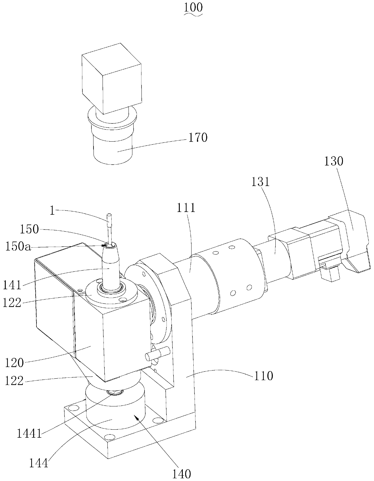
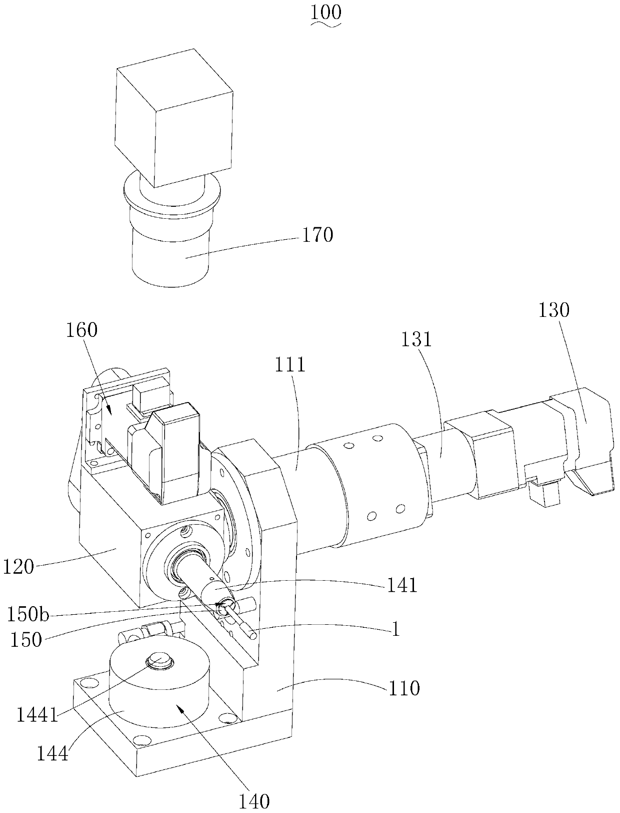
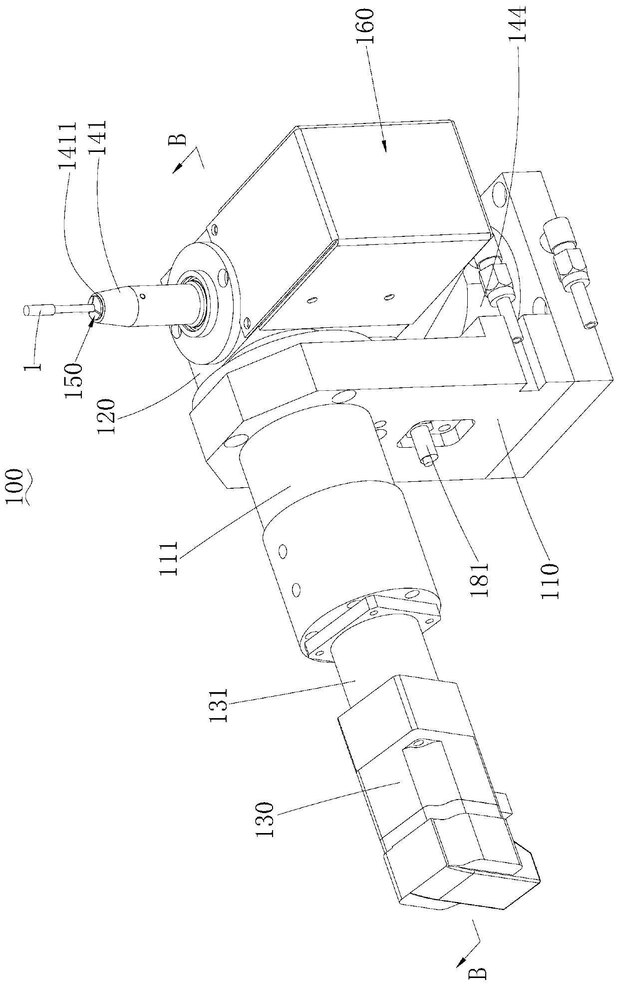
The invention belongs to the technical field of micro drill bit groove shape processing and relates to a numerical control working head. A first control motor can drive a shaft seat to rotate, so thata chuck connected to the shaft seat is capable of being switched between the loading and unloading position and the grinding position. When the chuck is at the loading and unloading position, the chuck extends in the longitudinal direction, so that a bar follows to be arranged in the longitudinal direction, and the bar is conveniently installed on and detached from the chuck; and a clamping and releasing mechanism is controlled by a controller to realize switching of the chuck between clamping and releasing. When the chuck is at the grinding position, the chuck extends in the transverse direction, so that the bar follows to be arranged in the transverse direction, and a grinding wheel grinds the bar conveniently. The overall structure of the numerical control working head occupies a smallspace, clamping and releasing of the bar can be automatically realized, the chuck can be switched between the loading and unloading position and the grinding position, and the working efficiency is high.

Description

technical field [0001] The invention belongs to the technical field of micro-drill groove processing, and more specifically relates to a numerical control working head. Background technique [0002] At present, cylindrical bars such as drill bits need to be ground, and the bar is usually clamped by a jig, and the clamping and loosening of the bar is realized by manually operating the jig. The fixture is installed on the slide table, and the position of the fixture is changed by manually sliding the slide table, so that the fixture can be switched between the loading and unloading position and the grinding wheel position, and the bar is fixed and disassembled at the loading and unloading position. For bar grinding, the configuration of the slide table will make the overall structure take up a lot of space. For the grinding of batch bars, each bar is manually clamped and loosened and the position of the clamp is adjusted. The operation is cumbersome, the manual work intensity...

Claims


Application Information

Patent Timeline
Patent Type & Authority Applications(China)
IPC IPC(8): B24B41/00B24B41/06B24B47/12B24B51/00
CPCB24B41/067B24B41/005B24B51/00B24B47/12
Inventor 韩庆红
Owner SHENZHEN JINZHOU PRECISION TECH
Learn More