Hydraulic hammer cylinder part

A technology of hydraulic breaker and components, which is applied in fluid pressure actuating devices, earth movers/excavators, construction, etc. It can solve problems such as piston return wear and pull piston full support balance, and achieve Great support and tight fit

Pending Publication Date: 2019-07-30
MAANSHAN KAMET HYDRAULIC MASCH MFG CO LTD
View PDF1 Cites 5 Cited by
  • Summary
  • Abstract
  • Description
  • Claims
  • Application Information

AI Technical Summary

Problems solved by technology

This patent effectively solves the problem of cylinder scuffing during the piston strike stroke, but still cannot solve the common problems of wear and strain during the piston return stroke and the balance of the entire piston support.

Method used


Image

  • Hydraulic hammer cylinder part
  • Hydraulic hammer cylinder part
  • Hydraulic hammer cylinder part

Examples


Embodiment 1

[0036] Example 1: Combining figure 2 , image 3 and Figure 4 Explain the technical solutions of claims 1, 2 and 7 of the invention;

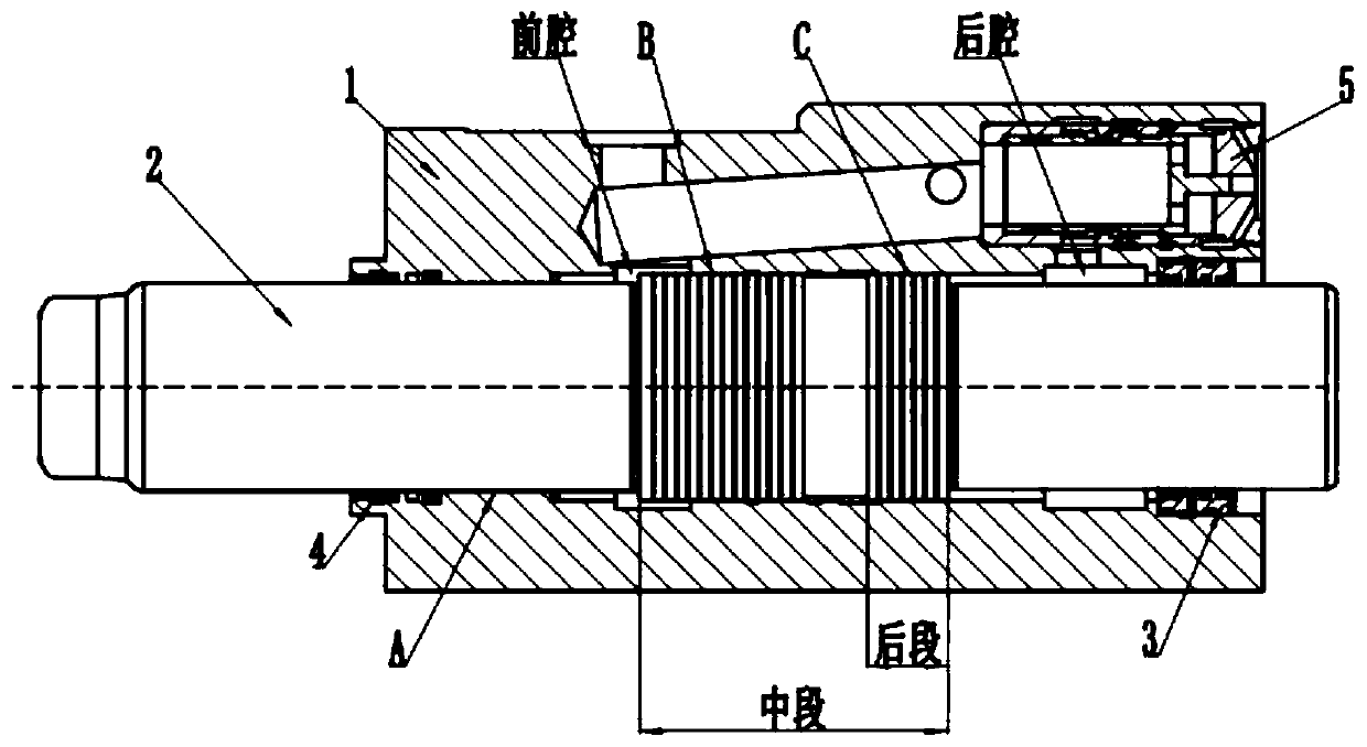
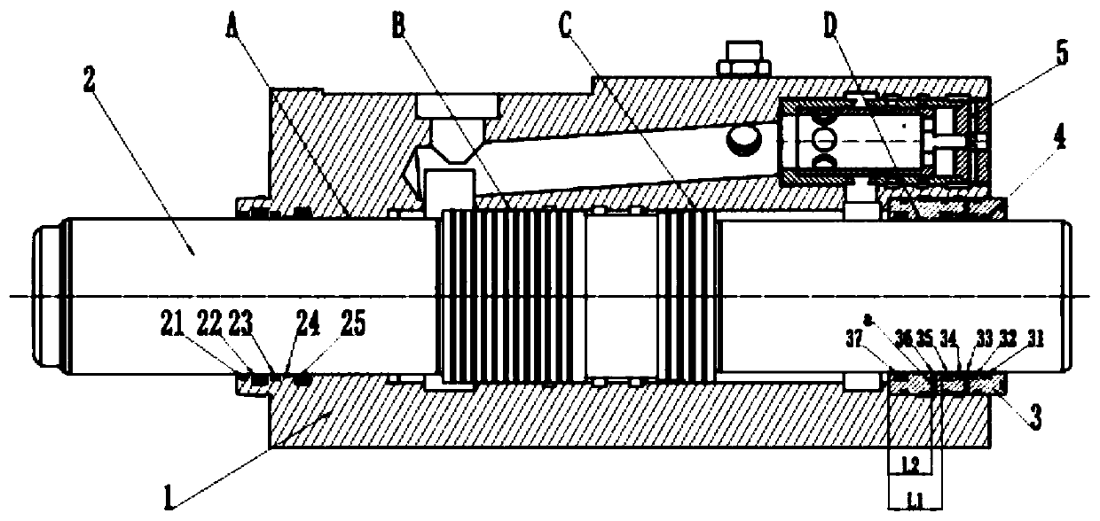
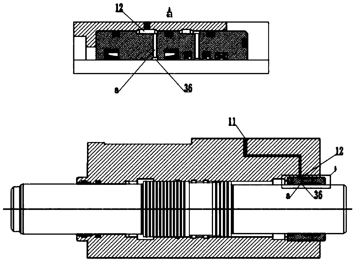
[0037] An embodiment of the present invention is a middle cylinder part of a hydraulic breaker, the middle cylinder part (see figure 2 ) includes: a middle cylinder body 1, a piston 2, a piston ring 3, a seal 4 and a reversing valve 5, and the inner hole structure of the piston ring 3 (see Figure 4 ) includes from right to left: air seal groove 31, oil seal groove 32, oil return groove 33, seal grooves 34 and 35; the technical solution of this embodiment is: the piston ring on the left side of the seal groove 35 3 The cylindrical section is lengthened to L1, and an oil supply groove 36 is added at the same time. A radial through hole a is arranged in the oil supply groove 36. The distance between the center line of the through hole a and the left end face is L2, and the through hole a and the middle cylinder body The high-pressure oil in...

Embodiment 2

[0038] Example 2: Combining figure 2 , Figure 5 Explain the technical solutions of invention claims 3, 4, and 6:

[0039] An embodiment of the present invention is a middle cylinder part of a hydraulic breaker, the middle cylinder part (see figure 2 ) includes: a middle cylinder body 1, a piston 2, a piston ring 3, a seal 4 and a reversing valve 5, and the inner hole structure of the piston ring 3 (see Figure 5 ) includes from right to left: air seal groove 31, oil seal groove 32, oil return groove 33, seal grooves 34 and 35; the technical solution of this embodiment is: the piston ring on the left side of the seal groove 35 3. The cylindrical section is lengthened to L1, and an oil supply groove 36 is added at the same time. A radial through hole a is arranged in the oil supply groove 36. The distance between the through hole a and the left end face is L2. The high-pressure oil inlet is connected, and the high-pressure oil is always passed through the oil supply groove...

Embodiment 3

[0040] Example 3: Binding figure 2 , Figure 6 Explanation of the technical solutions of invention claims 3 and 5:

[0041] An embodiment of the present invention is a middle cylinder part of a hydraulic breaker, the middle cylinder part (see figure 2 ) includes: a middle cylinder body 1, a piston 2, a piston ring 3, a seal 4 and a reversing valve 5, and the inner hole structure of the piston ring 3 (see Figure 5 ) includes from right to left: air seal groove 31, oil seal groove 32, oil return groove 33, seal grooves 34 and 35; the technical solution of this embodiment is: the piston ring on the left side of the seal groove 35 3. The cylindrical section is lengthened to L1, and an oil supply groove 36 is added at the same time. A radial through hole a is arranged in the oil supply groove 36. The distance between the through hole a and the left end face is L2. The high-pressure oil inlet port of the high-pressure oil is connected, and the high-pressure oil is always connect...


PUM


Abstract

The invention discloses a hydraulic hammer cylinder part. The hydraulic hammer cylinder part comprises a cylinder body, a piston, a piston ring, sealing parts and a reversing valve. According to the hydraulic hammer cylinder part, a left side piston ring cylindrical section of a leftmost sealing part groove of a piston ring inner hole is lengthened by L1, meanwhile, an oil feeding groove is additionally formed in the lengthened part, and a gap sealing section D is formed on the left side of the oil feeding groove, or one or two sealing part grooves are additionally formed in the left side of the oil feeding groove; and in the working process, high-pressure oil is always introduced into the gap sealing section D or the added sealing part grooves, so that the sealing parts in the sealing part grooves are simultaneously subjected to axial compression force and radial compression force under the action of the high-pressure oil, the sealing parts in the grooves are more tightly matched witha to-be-sealed surface, the great supporting effect is achieved on a postmedian section in the piston, so that the severe loss caused by scoring of the piston and the inner hole due to contact of thepiston and the inner hole of the cylinder is effectively avoided.

Description

technical field [0001] The invention relates to the field of hydraulic breakers, in particular to a cylinder part of a hydraulic breaker. Background technique [0002] The hydraulic breaker is a crushing tool that converts hydraulic energy into mechanical impact energy. Driven by high-pressure oil, it automatically completes the high-frequency vibration of the piston in the cylinder through the mutual feedback control of its own valve control system and the cylinder-piston system. The reciprocating motion converts the hydraulic energy into the impact energy of the piston to drive the chisel to perform striking motion, and outputs energy to achieve the purpose of breaking rocks. [0003] Cylinder parts of hydraulic breaker (see figure 1 ), mainly including the middle cylinder body, piston, piston ring, seal and reversing valve assembly. Reciprocating motion converts the hydraulic energy into the impact energy of the piston to drive the drill rod to strike. [0004] Cylinde...

Claims


Application Information

Patent Timeline
Patent Type & Authority Applications(China)
IPC IPC(8): E02F5/30F15B15/14F15B15/20
CPCE02F5/30E02F5/305F15B15/1414F15B15/1452F15B15/1457F15B15/1461F15B15/202
Inventor 赵培云孟宪三
Owner MAANSHAN KAMET HYDRAULIC MASCH MFG CO LTD
Why Eureka
Try Eureka