Eureka AIR delivers breakthrough ideas for toughest innovation challenges, trusted by R&D personnel around the world.

Converter sliding plate slag blocking hydraulic control device

A technology of control device and slide plate, which is applied in the direction of fluid pressure actuating device, manufacturing converter, fluid pressure actuating system components, etc. problems, to achieve significant economic benefits, improve quality, and improve the effect of response speed

Pending Publication Date: 2019-07-30
宣化钢铁集团有限责任公司
View PDF0 Cites 2 Cited by
  • Summary
  • Abstract
  • Description
  • Claims
  • Application Information

AI Technical Summary

Problems solved by technology

However, in the actual application of sliding slag blocking, due to the slow closing of the sliding plate by the hydraulic cylinder, part of the steel slag also flows into the ladle, which has a great impact on the amount of phosphorus returned to molten steel and affects the smelting of high-quality steel

Method used


Image

  • Converter sliding plate slag blocking hydraulic control device

Examples


Embodiment Construction

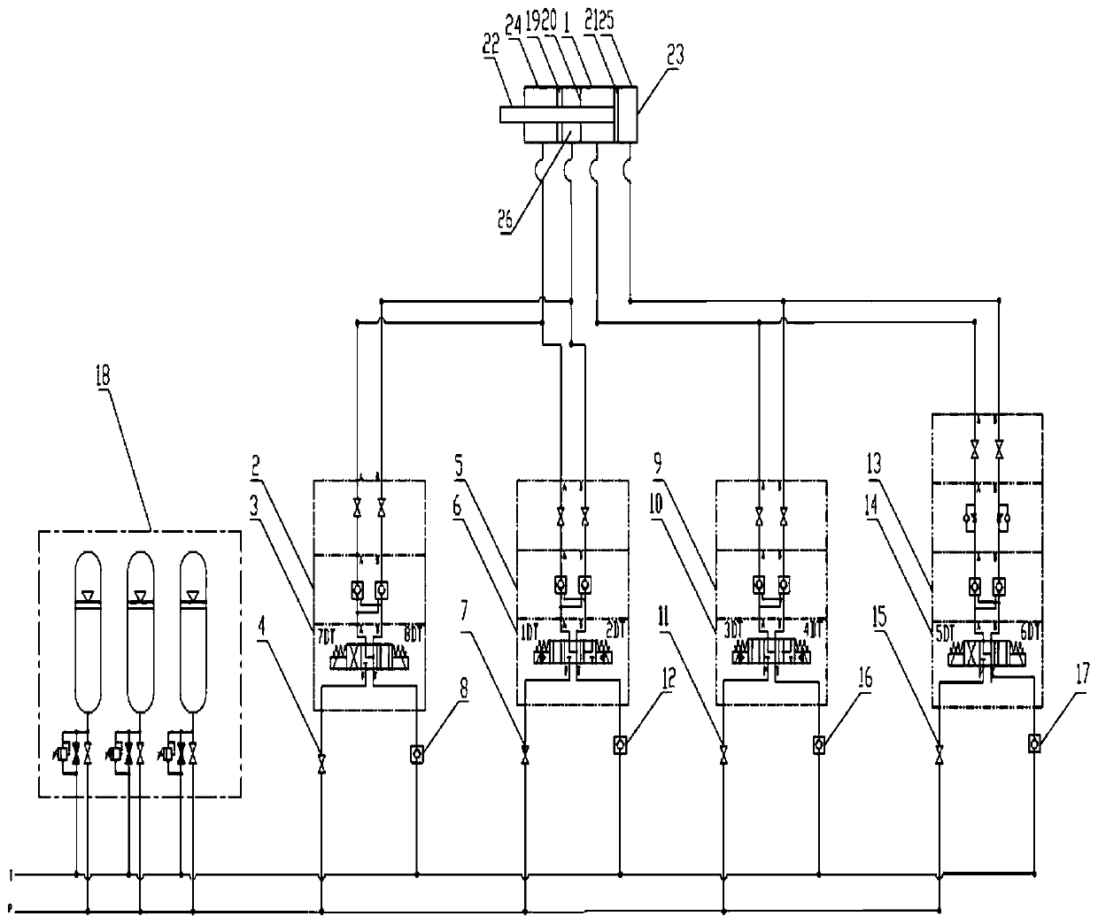
[0017] The present invention includes a composite hydraulic cylinder 1 , a first quick response control unit, a second quick response control unit, a first slow electromagnetic control unit, a second slow electromagnetic control unit and an accumulator group 18 .

[0018] As shown in the figure, the composite hydraulic cylinder 1 is composed of a first hydraulic cylinder 24 and a second hydraulic cylinder 25 . The first hydraulic cylinder 24 is made up of piston rod, cylinder barrel 23, first piston 19, dividing plate 20; The second hydraulic cylinder 25 is made up of piston rod, cylinder barrel 23, dividing plate 20, second piston 21; The first hydraulic cylinder 24 and the second hydraulic cylinder 25 share a piston rod, cylinder barrel 23, and partition 20. In the first hydraulic cylinder 24, the pressure is formed by the outer surface of the first piston 19, cylinder barrel 23, partition 20, and piston rod. Cavity 26.

[0019] As shown in the figure, the overall structure...


PUM


Abstract

The invention discloses a converter sliding plate slag blocking hydraulic control device and belongs to the technical field of converter steelmaking equipment. The converter sliding plate slag blocking hydraulic control device is used for carrying out hydraulic control on a converter sliding plate slag. According to the technical scheme, a composite hydraulic cylinder is composed of a first hydraulic cylinder and a second hydraulic cylinder, wherein the first hydraulic cylinder and the second hydraulic cylinder share a piston rod, a cylinder barrel and a partition plate, a pressure cavity is defined by the first piston, the cylinder barrel, the partition plate and the outer surface of the piston rod in the first hydraulic cylinder, a first fast response control unit is connected to a rod cavity and the pressure cavity of the first hydraulic cylinder through an oil pipe, a second fast-response control unit is connected to a rod cavity and a rodless cavity of the second hydraulic cylinder through an oil pipe, and a first slow-speed electromagnetic control unit and a second slow-speed electromagnetic control unit are connected with an oil pipe of the composite hydraulic cylinder through the oil pipe and the first fast-response control unit and the second fast-response control unit. According to the converter sliding plate slag blocking hydraulic control device, the response speedof the converter sliding plate slag can be effectively improved, and the sliding plate slag closing time meets the production requirements.

Description

technical field [0001] The invention relates to a hydraulic control device for slag blocking of a converter slide plate in a steelmaking plant, and belongs to the technical field of converter steelmaking equipment. Background technique [0002] The converter sliding plate slag blocking technology is the principle of transplanting the sliding nozzle of the ladle. The sliding nozzle device is installed at the original tapping hole of the converter, and the slag blocking and tapping are realized through the dislocation of the flow steel hole between the sliding sliding plate and the fixed sliding plate. Due to the harsher operating conditions, harsher environment and more limited space at the taphole of the converter, the sliding slide device is more special. The converter sliding plate slag blocking device is composed of a steel tapping hole, a fixed sliding plate, a sliding sliding plate, and a hydraulic system. The fixed sliding plate is fixed to the steel tapping hole, and ...

Claims


Application Information

Patent Timeline
Patent Type & Authority Applications(China)
IPC IPC(8): F15B11/08F15B11/04F15B21/08F15B1/02C21C5/46
CPCF15B11/08F15B11/04F15B21/08F15B1/02C21C5/46
Inventor 杨高瞻王宏斌李贵平胡泽东杨凡贾明雪赵贝贝贺玉军李琳伟赵高继
Owner 宣化钢铁集团有限责任公司
Why Eureka
Eureka Blog
Learn More