Wireless thermocouple and temperature measuring device using the same

A technology of temperature measuring device and thermocouple, which is applied to measuring devices, thermometers using electrical devices, and thermometers with electrical/magnetic components directly sensitive to heat, etc. Problems such as data usage, difficulty in reflecting the advantages of thermocouple testing, etc., are beneficial to grid management, cost saving, and good work stability.

Active Publication Date: 2019-07-30
杭州纵联科技有限公司
View PDF6 Cites 6 Cited by
  • Summary
  • Abstract
  • Description
  • Claims
  • Application Information

AI Technical Summary

Problems solved by technology

[0004] At the same time, in the prior art, it often takes long wires to transmit the weak thermal electromotive force signal sensed by the thermocouple to the display instrument, and the signal is an analog signal, so the thermal electromotive force signal is easily disturbed during the transmission process, affecting the data. Reliability; in addition, the cost of wire transmission is high and the maintenance is relatively difficult; at the same time, analog signals are not convenient for the use of data by the control system
At the same time, the existing technology uses compensation wires for cold junction compensation, but its structure is complex and cannot fully accurately reflect the actual temperature of the cold junction.
If the temperature of the measured target is relatively high, the temperature is easily transmitted to the cold end, resulting in a small difference between the temperature of the cold end and the hot end. Even if the temperature compensation method is used, it is difficult to reflect the testing advantages of the thermocouple. problems such as reduced service life

Method used


Image

  • Wireless thermocouple and temperature measuring device using the same
  • Wireless thermocouple and temperature measuring device using the same
  • Wireless thermocouple and temperature measuring device using the same

Examples


Embodiment Construction

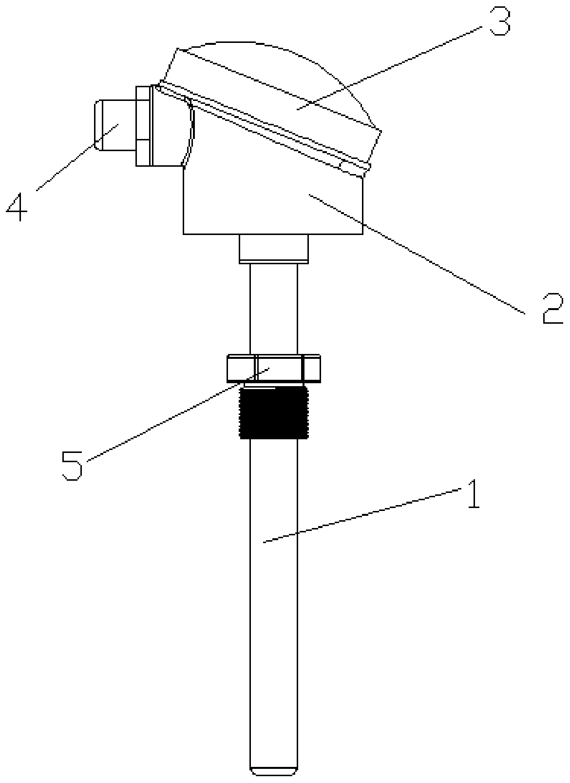
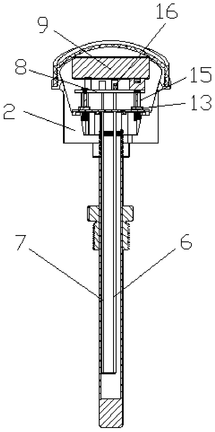
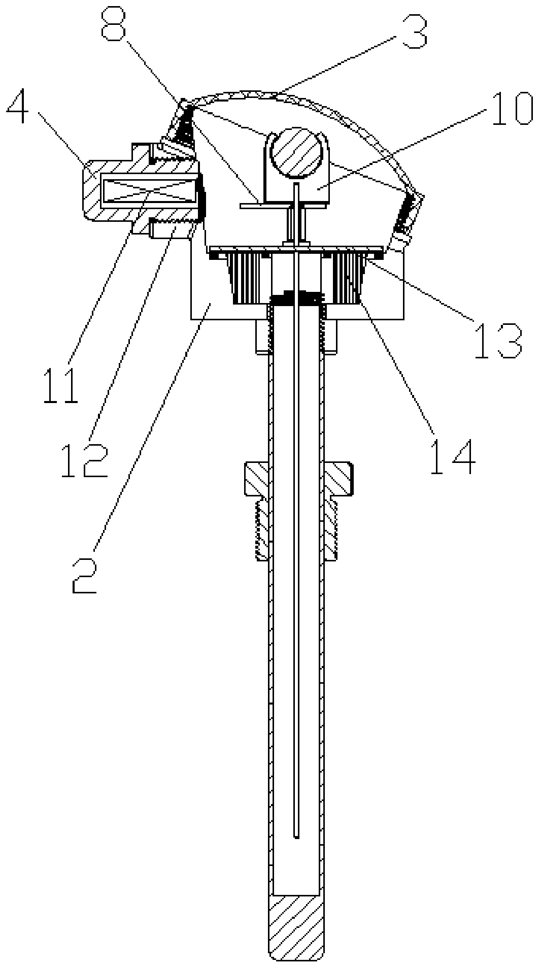
[0053] refer to Figure 1 to Figure 8 A wireless thermocouple and a temperature measuring device using the thermocouple are shown, including a protective cover 1, an electronic compartment 2, a circuit board 8, a thermocouple, a receiving host 31 and a cloud platform 32, and the protective cover 1 is connected to the electronic compartment 2 , the upper end of the electronic compartment 2 is provided with an electronic compartment cover 3, a connecting seat 5 is welded on the outside of the protective cover 1, and the connecting seat 5 is provided with threads, the thermocouple is arranged inside the protective cover 1, and the thermocouple One end extends to the inside of electronic storehouse 2 and is connected with circuit board 8, and described circuit board 8 is provided with data acquisition module 26, data front-end processing module 27, data processing module 28, wireless communication module 29, and data acquisition module 26 uses To collect the thermoelectromotive fo...


PUM


Abstract

The invention discloses a wireless thermocouple and a temperature measuring device using the same. The temperature measuring device comprises a receiving host, a protective sleeve, an electronic bin,a circuit board and the thermocouple; the thermocouple is arranged inside the protective sleeve; one end of the thermocouple extends to the inside of the electronic bin and is connected with the circuit board; the circuit board is provided with a data acquisition module, a data front-end processing module, a data processing module, and a wireless communication module; the thermoelectromotive forceis acquired from the thermocouple through the data acquisition module, and then the thermoelectromotive force is subjected to amplification, filtering and other processes through the data front-end processing module; analog signals are converted into digital signals through the data processing module; combined with the temperature characteristics of a cold end temperature compensation signal andthe thermocouple, the thermoelectromotive force is directly converted into the temperature and transmitted to the wireless communication module; and the wireless communication module transmits data tothe receiving host through a preset data transmission requirement and a communication protocol, and the receiving host receives and forwards the data to a cloud platform, so that the grid control ofthe temperature is realized.

Description

technical field [0001] The invention relates to a wireless thermocouple and a temperature measuring device using the thermocouple. Background technique [0002] In industrial production process, temperature is one of the important parameters that need to be measured and controlled. In temperature measurement, thermocouple or thermal resistance is widely used. It has many advantages such as simple structure, convenient manufacture, wide measurement range, high precision, small inertia and easy remote transmission of output signal. In addition, since the thermocouple or thermal resistance is an active sensor, no external power supply is required for measurement, and the energy consumption is low, so it is often used to measure the temperature of the gas or liquid in the furnace, the pipeline, and the surface temperature of the solid. [0003] Existing thermocouples or thermal resistances have different shapes due to needs, but their basic composition and structure are roughly...

Claims


Application Information

Patent Timeline
Patent Type & Authority Applications(China)
IPC IPC(8): G01K7/02G01K1/08G01K1/02G08C17/02G01K1/024
CPCG01K7/02G01K1/08G01K1/02G08C17/02
Inventor 张淼林詹才意
Owner 杭州纵联科技有限公司
Why Eureka
Try Eureka