Active receiver for connected RFID tags

A technology of RFID tags and receivers, applied in the field of near-field communication tags

Pending Publication Date: 2019-07-30
NXP BV
View PDF0 Cites 0 Cited by
  • Summary
  • Abstract
  • Description
  • Claims
  • Application Information

AI Technical Summary

Problems solved by technology

[0007] There may be a need to define a new RFID tag architecture that works through the same type of antenna signal as seen in the passive field powered case above, but that integrates passive as well as active tags in a single tag. Source Transfer Capability Both

Method used


Image

  • Active receiver for connected RFID tags
  • Active receiver for connected RFID tags
  • Active receiver for connected RFID tags

Examples


Embodiment approach

[0081] Any smart RFID tag application that requires both passive as well as active reverse modulation, and where an active receiver needs to be integrated with a passive front end in a tag that can also operate in field powered mode,

[0082]applications where a tag may need to communicate with an antenna of extremely small size in the presence of a battery,

[0083] Mobile Tag Communication System.

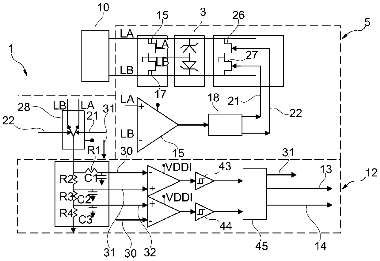
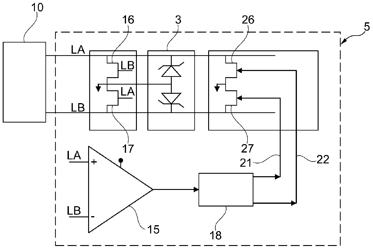
[0084] Reference number:

[0085] 1 RFID tag;

[0086] 3 voltage limiter;

[0087] 5 active receiver switching circuit;

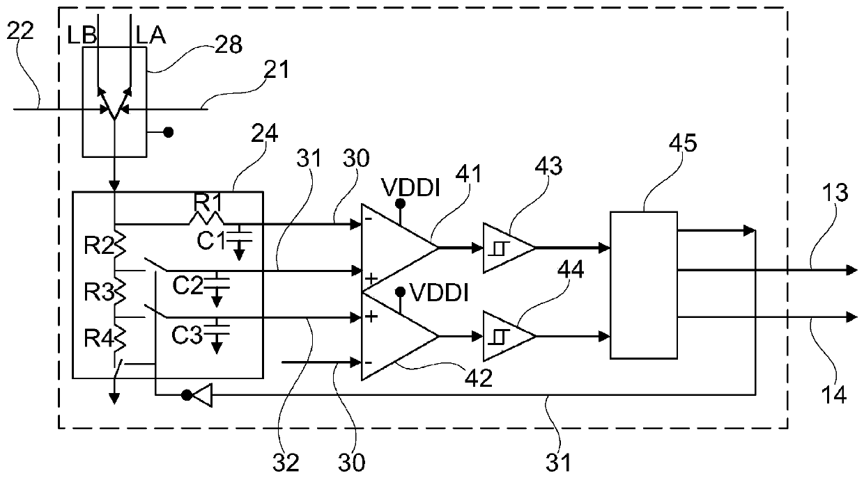
[0088] 8 Correcting the waveform signal 8;

[0089] 10 antennas;

[0090] 12 modulation detection circuit;

[0091] 13, 14 demodulate the signal;

[0092] 15 high-speed comparators;

[0093] 16, 17 switch;

[0094] 18 non-overlapping circuits;

[0095] 21, 22 recover the clock signal;

[0096] 24 filter circuit;

[0097] 26, 27 switch;

[0098] 28 Active full-wave rectifiers;

[0099] 30 filter signal;

[0100] 31 a first threshold voltage signa...


PUM


Abstract

A RFID tag (1) for communicating with an external reader comprises: two antenna connections (LA, LB) for connecting the RFID tag (1) to an antenna (10),an active receiver switch circuit (5) for receiving two input sinusoidal signals from the two antenna connections (LA, LB) and generating a rectified waveform signal (8),a modulation detection circuit (12) for receiving two input sinusoidal signalsfrom the two antenna connections (LA, LB) and generating a first demodulation signal (13) related to a 10% amplitude modulation of a RF field for communication between the reader and the RFID tag (1)and a second demodulation signal (14) related to a 100% amplitude modulation of a RF field for communication between the reader and the RFID tag (1).

Description

technical field [0001] The present invention relates to an active receiver for a connected RF tag. In particular, but not exclusively, the present invention relates to Near Field Communication (NFC) tags. Background technique [0002] Radio Frequency IDentification (RFID) tags, specifically, Near Field Communication (Near Field Communication, NFC) tags are having a huge impact in the contactless market. Especially as they move into infrastructure applications, tags that can communicate at higher distances become more attractive. [0003] Traditionally, RFID tags have been implemented with passive transmission capabilities. Such tags are available to the available radio frequency (Radio Frequency, RF) field and generate the RFID tag's internal power supply from the RF field to power the tag's internal systems, including analog and digital circuits (power-by-field) . Typically, this internal system usually consumes 10μA to 200μA. The available RF field may vary in the ran...

Claims


Application Information

Patent Timeline
Patent Type & Authority Applications(China)
IPC IPC(8): G06K19/077H04B5/00
CPCG06K19/07773G06K19/0775H04B5/77G06K19/0709G06K19/0715G06K19/0723H04B5/72G06K7/0008H01Q1/2225H01Q1/44
Inventor 扎尹帝普·吉里什卡马·达勒瓦迪
Owner NXP BV
Why Eureka
Try Eureka