
Motor mounting structure with electromagnetic induction type rotary transformer

A resolver and electromagnetic induction technology, applied in electromechanical devices, structural connections, electrical components, etc., can solve the problems of poor shock resistance, poor anti-shake ability, and can only be installed at the end of the motor shaft, achieving long service life and high resistance. The effect of strong low temperature capability and diversified installation methods

Active Publication Date: 2019-07-30
赛卓电子科技(上海)股份有限公司
View PDF9 Cites 4 Cited by
  • Summary
  • Abstract
  • Description
  • Claims
  • Application Information

AI Technical Summary

Problems solved by technology

[0006] Defects: The grating disk is fragile, easily polluted by oil and dust, resulting in signal loss, poor anti-jitter ability
[0009] Defects: The demagnetization of the magnet at high temperature causes the signal accuracy to decrease; the magnet magnetization technology requires high requirements, especially the uneven magnetization at the junction of the N and S poles leads to distortion of the sine wave signal, and the output signal accuracy decreases; the installation accuracy is high and the shock resistance is poor; only Can be installed at the end of the motor shaft
[0012] Disadvantages: The traditional resolver is large in size and weight, requires a large installation space, and causes troubles to the overall design of the motor
[0013] The above schemes have different degrees of defects in terms of motor installation methods, etc.

Method used


Image

  • Motor mounting structure with electromagnetic induction type rotary transformer
  • Motor mounting structure with electromagnetic induction type rotary transformer
  • Motor mounting structure with electromagnetic induction type rotary transformer

Examples


Embodiment Construction

[0041] The present invention will be described in detail below in conjunction with specific embodiments. The following examples will help those skilled in the art to further understand the present invention, but do not limit the present invention in any form. It should be pointed out that for those of ordinary skill in the art, several changes and modifications can be made without departing from the concept of the present invention.

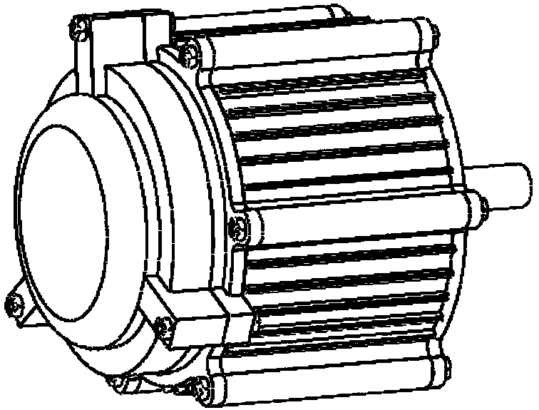
[0042] figure 1 It is a schematic diagram of the appearance of the inner rotor motor of the present invention.

[0043] The inner rotor motor uses the wire package in the middle of the motor as a rotating body to output torque, and the magnetic steel of the motor is fixed differently.

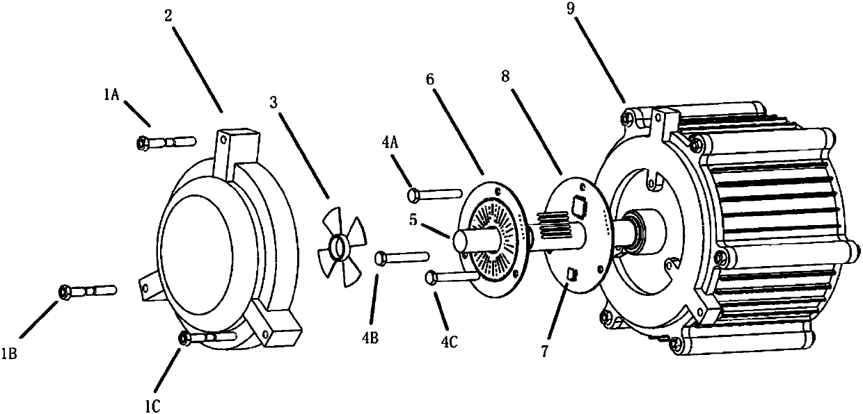
[0044] figure 2 It is a schematic diagram of the explosive structure of the inner rotor motor of the present invention.

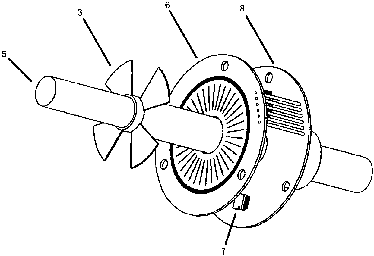
[0045] As shown in the figure, the wire package in the middle of the motor body 9 is connected to the motor shaft 5 and drives it to rotate; the sta...


PUM


Abstract

The invention provides a motor mounting structure with an electromagnetic induction type rotary transformer. The motor mounting structure comprises a motor body, the electromagnetic induction type rotary transformer and a motor controller module, wherein the electromagnetic induction type rotary transformer is connected with the motor body, and is used for outputting a coding signal; and the motorcontroller module is used for receiving the coding signal and controlling the motor body. Compared with the prior art, the motor mounting structure with the electromagnetic induction type rotary transformer has the following advantages that 1) the mounting modes of the motor are diversified and simple, and installation in a shaft penetrating manner, a shaft end manner and a shaft side edge mannercan be realized; 2) a non-contact induction mode is adopted, so that the service life is long; 3) the structure is anti-jitter, oil-resistant and anti-electromagnetic interference and high in high-temperature resistance and high in low-temperature resistance; and 4) an output signal form can be adapted to any motor controller interface.

Description

Technical field [0001] The invention relates to a motor mounting structure with an electromagnetic induction type resolver. Background technique [0002] The concept of Industry 4.0 is being widely spread around the world, which represents the future development trend of intelligent industry, and in the new generation of motor manufacturing, fast and efficient is the clear trend of technological development. The requirements for motor control in more and more applications and fields have not only stopped at the general-purpose inverter and speed control that meet energy-saving requirements, but precise position control has become a new demand point. [0003] Motor position detection and feedback are completed by the motor position encoder, so an excellent motor position encoder largely determines the performance of the motor in terms of energy saving, high efficiency, precision and interoperability. The current motor position encoder solutions on the market mainly include: [0004]...

Claims


Application Information

Patent Timeline
Patent Type & Authority Applications(China)
IPC IPC(8): H02K11/225
CPCH02K11/225
Inventor 陶骋杨莹吴小芳付继祥
Owner 赛卓电子科技(上海)股份有限公司
Learn More