Check patentability & draft patents in minutes with Patsnap Eureka AI!

Switching circuit for seamlessly switching voltage reduction working mode and direct-connection working mode, and realization method

A working mode, seamless switching technology, used in output power conversion devices, conversion equipment without intermediate conversion to AC, electrical components, etc., can solve the problem of large VOUT ripple, BOOT voltage drop, VIN and VOUT voltage difference Larger problems, to achieve the effect of eliminating ripple voltage, reducing voltage difference, and stabilizing output

Inactive Publication Date: 2019-07-30
SOUTHCHIP SEMICON TECH SHANGHAI CO LTD
View PDF5 Cites 5 Cited by
  • Summary
  • Abstract
  • Description
  • Claims
  • Application Information

AI Technical Summary

Problems solved by technology

[0005] The purpose of the present invention is to provide a conversion circuit for seamlessly switching between buck and direct working modes, which solves the problem that the BOOT voltage will drop in the existing solutions, and the BOOT must be periodically supplemented with energy, which may cause VOUT to drop. The problem of large waves; and when the load current is large and VIN is low, the voltage difference between VIN and VOUT will be large

Method used


Image

  • Switching circuit for seamlessly switching voltage reduction working mode and direct-connection working mode, and realization method
  • Switching circuit for seamlessly switching voltage reduction working mode and direct-connection working mode, and realization method
  • Switching circuit for seamlessly switching voltage reduction working mode and direct-connection working mode, and realization method

Examples


Embodiment

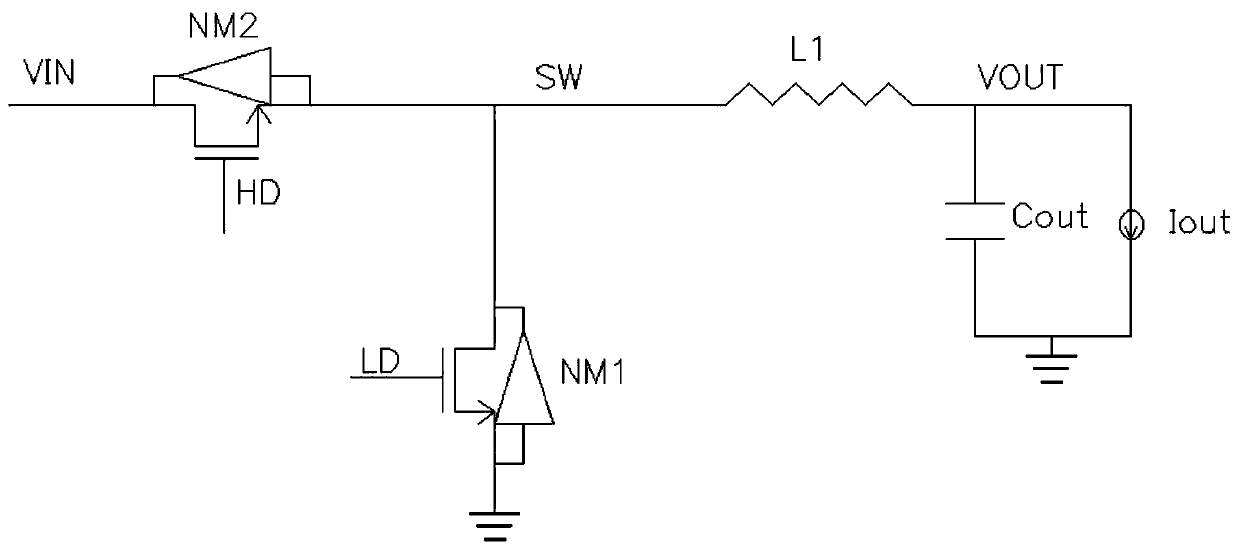
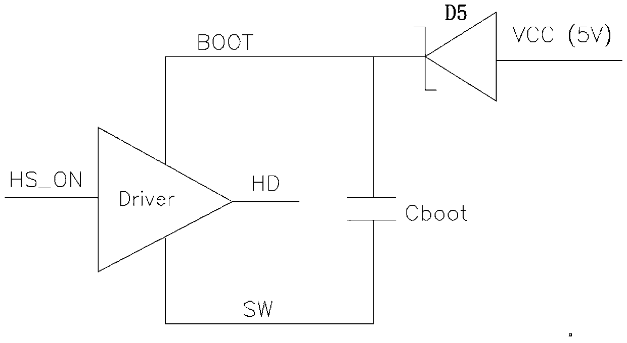
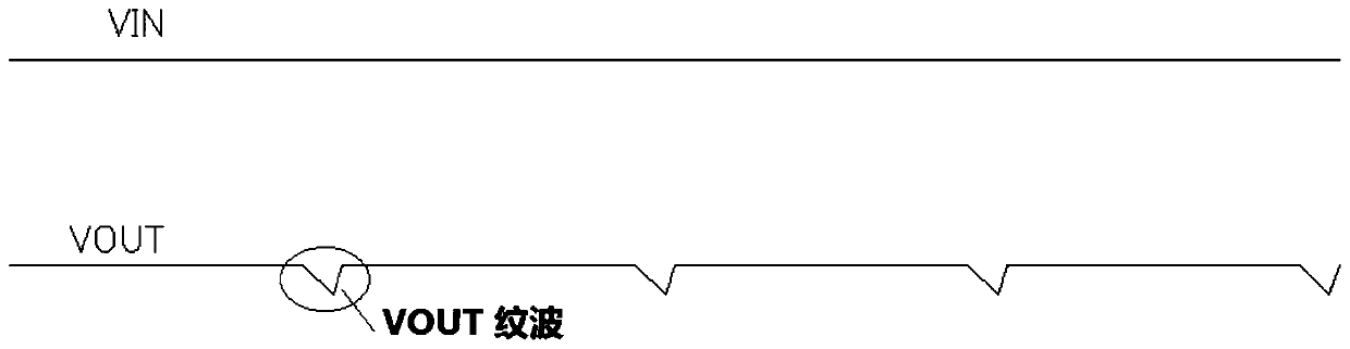
[0050] Such as Figure 4 As shown, the present invention discloses a conversion circuit for seamlessly switching the step-down and straight-through operating modes, including a step-down circuit with a voltage input terminal VIN and a voltage output terminal VOUT, which provides a high level for the step-down circuit to make the step-down circuit The high-voltage bootstrap circuit supporting the straight-through working mode also includes a BOOT automatic boost circuit for eliminating the ripple voltage at the voltage output terminal VOUT when the voltage input terminal VIN is lower than the voltage output terminal VOUT.

[0051] Such as Figure 5 As shown, the BOOT automatic boosting circuit of the present invention includes a comparator OP1, a charge pump automatic boosting circuit connected to the output terminal EN_CP of the comparator OP1, after being connected in series, one end is connected to the voltage input terminal VIN, and the other end is connected to the voltage...


PUM


Abstract

The invention discloses a switching circuit for seamlessly switching a voltage reduction working mode and a direct-connection working mode. The switching circuit comprises a voltage reduction circuitwith a voltage input end VIN and a voltage output end VOUT, a high-voltage bootstrap circuit for providing a high level to the voltage reduction circuit to enable the voltage reduction circuit to support the direct-connection working mode, and a BOOT automatic boosting circuit used for eliminating a ripple voltage generated by the voltage output end VOUT when the voltage input end VIN is lower than the voltage output end VOUT. According to the switching circuit, the relation between VIN and VOUT is automatically detected through a comparator, and when VIN is close to VOUT, the high level output by the comparator controls the automatic boosting circuit of a charge pump to work, so that the purpose of stabilizing the BOOT voltage is achieved, the output voltage VOUT is stabilized, and the ripple voltage is eliminated; when VIN is lower than VOUT and the VIN voltage is relatively low, a mode that two or more than two charge pump automatic boosting circuits are connected in a cascaded modeis adopted, so that the VGS voltage difference on a MOS transistor NM2 is improved, and the on-resistance Rdson of the MOS transistor NM2 is reduced; and under the condition of the same output current IOUT, the voltage difference of VIN and VOUT is reduced, and the purpose of enabling VOUT to be close to VIN is achieved.

Description

technical field [0001] The invention relates to the field of integrated circuit design, in particular to a conversion circuit for seamlessly switching between step-down and straight-through operating modes and a realization method. Background technique [0002] Conventional buck converters can only work where the input voltage is higher than the output voltage; when the input voltage is lower than or close to the output voltage, the converter cannot work properly. in such as figure 1 In the step-down circuit shown, when VIN is lower than VOUT, if you want to support the through mode and VOUT can output stably, you need to maintain the HD signal at a high level for a long time. HD by eg figure 2 The bootstrap circuit shown is generated, but because the related drive circuit of BOOT has current consumption, the BOOT circuit boosted by the bootstrap circuit, if the bootstrap circuit cannot continue to work, the voltage of BOOT will drop, As a result, the voltage of HD drops...

Claims


Application Information

Patent Timeline
IPC IPC(8): H02M3/07H02M1/14
CPCH02M1/14H02M3/07
Inventor 李强卞坚坚阮晨杰
Owner SOUTHCHIP SEMICON TECH SHANGHAI CO LTD
Features
  • R&D
  • Intellectual Property
  • Life Sciences
  • Materials
  • Tech Scout
  • Unparalleled Data Quality
  • Higher Quality Content
  • 60% Fewer Hallucinations
Learn More